Table of Contents
Advertisement
Quick Links
Download this manual
See also:
Installation Manual
Advertisement
Table of Contents

Related Manuals for Allied Telesis AT-MCR1


Summary of Contents for Allied Telesis AT-MCR1
-
Page 1: Media Converter
Media Converter Chassis AT-MCR1 Installation Guide PN 613-000326 Rev A... - Page 2 Allied Telesis, Inc. has been advised of, known, or should have known, the possibility of such damages.
-
Page 3: Electrical Safety And Emission Compliance Statement
Compliance Statement Standards: This product meets the following standards. U.S. Federal Communications Commission Declaration of Conformity Manufacturer Name: Allied Telesis, Inc. Declares that the product: Media Converter Chassis Model Numbers: AT-MCR1 This product complies with FCC Part 15B, Class B Limits: This device complies with part 15 of the FCC Rules. -
Page 4: Translated Safety Statements
FCC Part 15 Class B Immunity EN55024 Electrical Safety EN60950 (TUV), UL 60950-1 ( CSA C22.2 Translated Safety Statements Important: When you see the , go to the Allied Telesis website www.alliedtelesis.com for the translated safety statement in your language. -
Page 5: Table Of Contents
Selecting a Site ..............14 Reviewing Safety Guidelines..........15 Installing a Media Converter in an AT-MCR1 Chassis ....16 Installing an AT-MCR1 Chassis On a Table or Desktop .....18 Installing an AT-MCR1 Chassis Under a Table......19 Wall-Mounting an AT-MCR1 Chassis..........22 Installing an AT-MCR1 Chassis in a Rack........24 Powering On an AC-Powered Chassis........26... - Page 6 Contents Chapter 3: Troubleshooting ............35 Appendix A: Technical Specifications ........37 Physical ..................37 Temperature ................37 Electrical Rating................37 Safety and Electromagnetic Emissions Certifications ....38 Compliance Standards ..............38 Pinout Assignments..............39...
-
Page 7: Preface
Preface This guide contains instructions on how to install an AT-MCR1 Fast Ethernet Switch. How This Guide is Organized This guide contains the following chapters and appendices: Chapter 1, ”Overview” on page 11 Chapter 2, ”Installation” on page 13 Chapter 3, ”Troubleshooting” on page 35 Appendix A, ”Technical Specifications”... -
Page 8: Document Conventions
Preface Document Conventions This document uses the following conventions: Note Notes provide additional information. Caution Cautions inform you that performing or omitting a specific action may result in equipment damage or loss of data. Warning Warnings inform you that performing or omitting a specific action may result in bodily injury. -
Page 9: Where To Find Web-Based Guides
AT-MCR1 Media Converter Chassis Installation Guide Where to Find Web-based Guides The installation and user guides for all Allied Telesis products are available in portable document format (PDF) on our web site at www.alliedtelesis.com. You can view the documents online or... -
Page 10: Contacting Allied Telesis
Support group through the Allied Telesis web site: www.alliedtelesis.com. Sales or Corporate Information You can contact Allied Telesis for sales or corporate information on our web site: www.alliedtelesis.com. To find the contact information for your country, select Contact Us -> Worldwide... -
Page 11: Chapter 1 Overview
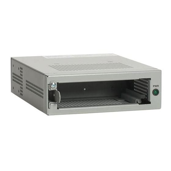
Chapter 1 Overview The AT-MCR1, shown in Figure 1, is a chassis with internal power designed to house one unit of an ATI media converter product. The AT-MCR1 chassis provides convenient installation options In addition to be desktop usage, it can also be mounted under a table, on the wall, as well as in an industry standard 19”... -
Page 12: Key Features
Chapter 1: Overview Key Features The AT-MCR1 chassis has the following features: LED for unit status One slot for an ATI standard media converter Internal AC/DC power supplies Desktop, wall-mount, under-table mount, or rack-mount installation Status LEDs Refer to Table 1 for a description of the chassis LED. -
Page 13: Chapter 2: Installation
This section contains the procedures for installing the chassis. Verifying the Package Contents Make sure the following items are included in your package. If any item is missing or damaged, contact your Allied Telesis sales representative for assistance. One AT-MCR1 Media Converter Chassis... -
Page 14: Selecting A Site
Chapter 2: Installation Selecting a Site Be sure to observe the following requirements when choosing a site for your chassis. Make sure you are placing the chassis in a dust-free and moisture-free environment. Do not block the ventilation openings on the unit. Allow at least 10 centimeters (4 inches) of space at the front and back of the unit for ventilation. -
Page 15: Reviewing Safety Guidelines
AT-MCR1 Media Converter Chassis Installation Guide Reviewing Safety Guidelines Review the following safety guidelines before installing the chassis. Warning Power cord is used as a disconnection device. To de- energize equipment, disconnect the power cord. Caution Pluggable Equipment: The socket outlet should be installed near the equipment and should be easily accessible. -
Page 16: Installing A Media Converter In An At-Mcr1 Chassis
Chapter 2: Installation Installing a Media Converter in an AT-MCR1 Chassis To install a media converter in the AT-MCR1 chassis, perform the following procedure: Remove all the items from the packaging of both the ATI media converter and the AT-MCR1 chassis and store the packaging material in a safe place. - Page 17 AT-MCR1 Media Converter Chassis Installation Guide Align the mounting guide on the media converter, with the media converter positioning on its side with the top cover on the left and the base plat on the right, as shown in Figure 4.
-
Page 18: Installing An At-Mcr1 Chassis On A Table Or Desktop
Chapter 2: Installation Installing an AT-MCR1 Chassis On a Table or Desktop To install the chassis on a table or desktop, perform the following procedure: Turn the AT-MCR1 chassis over. Attach the four protective rubber feet to the bottom of the chassis, as shown in Figure 6. -
Page 19: Installing An At-Mcr1 Chassis Under A Table
Note Prior to being installed under the table, the AT-MCR1 chassis should be wired and cabled first. For instructions, refer to “Powering On an AC-Powered Chassis” on page 26 and “Wiring and Powering On a DC-Powered Chassis”... - Page 20 Chapter 2: Installation Turn the chassis over and attach the two mounting brackets (provided) to the sides of the chassis using the bracketmounting screws (provided), as shown in Figure 7. 1052 Figure 7. Attaching Brackets for Under-Table Installation Position and mount the chassis under the table using the mounting screws (not provided), as shown in Figure 8.
- Page 21 AT-MCR1 Media Converter Chassis Installation Guide For cabling instructions, refer to the installation guide that comes with the ATI media converter. For powering up instructions, refer to “Powering On an AC- Powered Chassis” on page 26.
-
Page 22: Wall-Mounting An At-Mcr1 Chassis
Wall-Mounting an AT-MCR1 Chassis The chassis can be mounted vertically on a wall using the mounting brackets that come with the unit. To wall-mount an AT-MCR1 chassis, perform the following procedure: If attached, remove the rubber feet, data cables, and power cord from the chassis. - Page 23 AT-MCR1 Media Converter Chassis Installation Guide Position and mount the chassis onto the wall using the mounting screws, as shown in Figure 10. 1054 Figure 10. Mounting the Chassis onto the Wall Make sure that the chassis is securely mounted onto the wall.
-
Page 24: Installing An At-Mcr1 Chassis In A Rack
If attached, remove the rubber feet, data cables, and power cord from the chassis. Attach one of the provided mounting brackets to the right side of the AT-MCR1 chassis using the bracketmounting screws that come with the unit, as shown in Figure 11. 1055... - Page 25 AT-MCR1 Media Converter Chassis Installation Guide Mount the AT-MCR1 chassis in a 19” or 23” rack using the rackmounting screws (not provided), as shown in Figure 12. 1056 Figure 12. Mounting the Chassis in a Rack Make sure that the chassis is securely mounted in the rack.
-
Page 26: Powering On An Ac-Powered Chassis
Chapter 2: Installation Powering On an AC-Powered Chassis To apply power to an AC-powered AT-MCR1 chassis, perform the following procedure: Install the retaining clip onto the chassis., as shown in Figure 13. 1022 Figure 13. Installing Power Cord Retaining Clip onto Chassis Position the power cord retaining clip in the up position, as shown in Figure 14. - Page 27 AT-MCR1 Media Converter Chassis Installation Guide Plug the power cord into the power connector on the back of the chassis, as shown in Figure 15. 1057 Figure 15. Plugging Power Cord to Chassis Secure the cord by lowering the power cord retaining clip, as shown in Figure 16.
- Page 28 Chapter 2: Installation Plug the other end of the power cord into a wall outlet, as shown in Figure 17. 1060 Figure 17. Plugging Power Cord to Wall Outlet Warning The power cord is used as a disconnection device. To de- energize equipment, disconnect the power cord.
-
Page 29: Wiring And Powering On A Dc-Powered Chassis
AT-MCR1 Media Converter Chassis Installation Guide Wiring and Powering On a DC-Powered Chassis For a chassis that comes with a DC terminal block, perform the following procedure: Before attaching wires to the DC terminal block at the back of the chassis, review the following warning:... - Page 30 Chapter 2: Installation symbols above the terminal block, as shown in Figure 18. 40-60VDC 1058 Figure 18. DC Terminal Block With a 14-gauge wire-stripping tool, strip the three wires in the tray cable coming from the DC input power source to 8mm ±...
- Page 31 AT-MCR1 Media Converter Chassis Installation Guide Warning When installing this equipment, always ensure that the power supply ground connection is installed first and disconnected last. 40-60VDC 1059 Figure 20. Inserting Wires into a DC Terminal Block Connect the positive feed wire to the terminal block marked (+).
- Page 32 Chapter 2: Installation Secure the tray supply cable near the rack framework using multiple cable ties to minimize the chance of the connections being disturbed by casual contact with the wiring. Use at least four cable ties, separated four inches apart. Locate the first one within six inches of the terminal block.
-
Page 33: Warranty Registration
AT-MCR1 Media Converter Chassis Installation Guide Warranty Registration When you have finished installing the product, register your product by completing the enclosed warranty card and sending it in. You can also fill out the registration online by selecting “Warranties” under “Support & Services” from... -
Page 35: Chapter 3 Troubleshooting
Verify that the chassis and end-nodes are operating with the same duplex mode. If you are still experiencing problems after testing and troubleshooting the installation, refer to “Contacting Allied Telesis” on page 10. For support information, visit our web site at www.alliedtelesis.com. -
Page 37: Appendix A: Technical Specifications
Appendix A Technical Specifications Physical Dimensions: W x D x H 100 mm x 78.5 mm x 26 mm (3.93 in x 3.09 in x 1.02 in) Weight: .27 kg (0.60 labs) Temperature Operating Temperature: 0° C to 40° C (32°... -
Page 38: Safety And Electromagnetic Emissions Certifications
Appendix A: Technical Specifications Safety and Electromagnetic Emissions Certifications RFI Emissions FCC Part 15 Class B Immunity EN55024 Electrical Safety UL 60950 ( EN60950 (TUV), CE Compliance Standards IEEE 802.3 – Ethernet IEEE 802.3i – 10Base-T IEEE 802.3u – 100Base-TX IEEE 802.3x –... -
Page 39: Pinout Assignments
AT-MCR1 Media Converter Chassis Installation Guide Pinout Assignments Figure 21 shows the pinout assignments for the RJ-45 connector. Figure 21. RJ-45 Pin Assignments Figure 2 lists the 10Base-T/100Base-TX connector pins and their signals when the port is operating in either MDI or MDI-X configuration.
Need help?
Do you have a question about the AT-MCR1 and is the answer not in the manual?
Questions and answers