
Related Manuals for Allied Telesis AT-DMC1000/SC


Summary of Contents for Allied Telesis AT-DMC1000/SC
-
Page 1: Installation Guide
AT-DMC1000/100 Series Desktop Mini Media Converters AT-DMC1000/SC AT-DMC1000/ST AT-DMC1000/LC AT-DMC100/SC AT-DMC100/ST AT-DMC100/LC Installation Guide 613-002144 Rev C... - Page 2 Allied Telesis, Inc. has been advised of, known, or should have known, the...
-
Page 3: Industry Canada
Electrical Safety and Emissions Standards This section contains the following: “US Federal Communications Commission” “Industry Canada” “Emissions, Immunity and Electrical Safety Standards” on page 4 “Translated Safety Statements” on page 4 US Federal Communications Commission Radiated Energy Note This equipment has been tested and found to comply with the limits for a Class A digital device pursuant to Part 15 of FCC Rules. - Page 4 Electrical Safety EN60950-1 (TUV), UL 60950-1 ( Warning Laser Safety: EN60825 Translated Safety Statements Important: The indicates that a translation of the safety statement is available in a PDF document titled Translated Safety Statements on the Allied Telesis website at www.alliedtelesis.com/support.
-
Page 5: Table Of Contents
Contacting Allied Telesis..........................13 Chapter 1 : Overview ............................. 15 Introduction ..............................16 Features ..............................17 AT-DMC1000/SC, AT-DMC1000/ST, AT-DMC1000/LC ............... 17 AT-DMC100/SC, AT-DMC100/ST, AT-DMC100/LC ..............17 Twisted-Pair Port ..........................18 Fiber Connection ..........................18 Auto MDI/MDI-X ..........................18 LEDs..............................19 Smart MissingLink™... - Page 6 Contents...
- Page 7 Figure 13: Media Converter Back Panel..........................26 Figure 14: Media Converter Bottom Panel .......................... 27 Figure 15: AT-DMC1000/SC and AT-DMC100/SC Shipping Package Contents ..............37 Figure 16: AT-DMC1000/ST and AT-DMC100/ST Shipping Package Contents ..............37 Figure 17: AT-DMC1000/LC and AT-DMC100/LC Shipping Package Contents ..............38 Figure 18: Wall-Mount Kit Shipping Package Contents.......................
- Page 8 List of Figures...
- Page 9 Tables Table 1. Media Converter LED Functional Descriptions .....................20 Table 2. Physical Specifications ............................55 Table 3. Environmental Specifications ..........................55 Table 4. Power Specifications ............................56 Table 5. Safety and Electromagnetic Emissions Certifications ...................56 Table 6. MDI Pin Signals (100 Mbps) ..........................57 Table 7.
- Page 10 List of Tables...
-
Page 11: Preface
Preface This preface contains the following sections: “Symbol Conventions” on page 12 “Contacting Allied Telesis” on page 13 This guide contains the installation instructions for the following Desktop Mini Media Converters. AT-DMC1000/SC AT-DMC1000/ST AT-DMC1000/LC AT-DMC100/SC ... -
Page 12: Symbol Conventions
Symbol Conventions This document uses the following conventions: Note Notes provide additional information. Caution Cautions inform you that performing or omitting a specific action may result in equipment damage or loss of data. Warning Warnings inform you that performing or omitting a specific action may result in bodily injury. -
Page 13: Contacting Allied Telesis
AT-DMC1000/100 Series Desktop Mini Media Converter Installation Guide Contacting Allied Telesis If you need assistance with this product, you may contact Allied Telesis technical support by going to the Support & Services section of the Allied Telesis web site at www.alliedtelesis.com/support. You can find links for... -
Page 15: Chapter 1 : Overview
“Front and Back Panels” on page 25 “Twisted-Pair Port” on page 28 “Reset the Media Converter” on page 29 This chapter describes the following Desktop Mini Media Converters: AT-DMC1000/SC AT-DMC1000/ST AT-DMC1000/LC AT-DMC100/SC ... -
Page 16: Introduction
100Mbps fiber networks (AT-DMC100/SC, AT-DMC100/ST, and AT-DMC100/LC): This offers a cost-effective method for integrating fiber-optic cabling into a 100/1000 UTP environment. Operate at 1000Mbps full duplex (AT-DMC1000/SC, AT-DMC1000/ST, and AT-DMC1000/LC) or 100 Mbps full duplex (AT-DMC100/SC, AT-DMC100/ST, and AT-DMC100/LC). -
Page 17: Features
AT-DMC1000/100 Series Desktop Mini Media Converter Installation Guide Features Here are the key features of the AT-DMC1000/100 Series Desktop Mini Media Converters: AT-DMC1000/SC, AT-DMC1000/ST, AT-DMC1000/LC 1000Base-SX fiber-optic port Auto Negotiation and Auto MDI/MDI-X on 1000Base-T twisted-pair (copper) port. The twisted-pair port will auto-negotiate to 1000Mpbs, full duplex operation. -
Page 18: Twisted-Pair Port
RJ45 connector Fiber Connection The AT-DMC1000/100 Series media converters support the following transceiver fiber connections: The AT-DMC1000/SC has a fixed dual fiber SC 1000-X connection. The AT-DMC1000/ST has a fixed dual fiber ST 1000-X connection. The AT-DMC1000/LC has a fixed dual fiber LC 1000-X connection. -
Page 19: Leds
AT-DMC1000/100 Series Desktop Mini Media Converter Installation Guide LEDs Figure 1 shows the SYS and copper port LEDs. LINK/ACT DUP/COL Figure 1. SYS and Copper Port LEDs Figure 2 shows the fiber port LED. AT-DMC1000/SC AT-DMC100/SC LINK/ACT AT-DMC1000/ST AT-DMC100/ST LINK/ACT AT-DMC1000/LC... -
Page 20: Table 1. Media Converter Led Functional Descriptions
Chapter 1: Overview Table 1 describes the media converter’s LEDs. Table 1. Media Converter LED Functional Descriptions State Description The media converter is not receiving power or is not operational and will not pass traffic. Solid Green The media converter is operational. (with Heartbeat) Note: The SYS LED will flicker briefly at a... -
Page 21: Smart Missinglink™ (Sml)
AT-DMC1000/100 Series Desktop Mini Media Converter Installation Guide Table 1. Media Converter LED Functional Descriptions (Continued) State Description The port has not established a link. Steady The port has an established link to a Green network device, but it is not transmitting or receiving network packets. -
Page 22: Sml Example Scenarios With Two Connected Media Converters
Chapter 1: Overview Figure 3 shows media converter and end node LINK/ACT LED behavior with SML enabled under normal conditions. End Node End Node AT-DMC1000 Copper Cable Fiber Cable Copper Fiber Link Up Link Up LINK/ACT LINK/ACT Link LED On Link LED On LED On LED On... -
Page 23: Figure 6: Sml In Normal Condition With Two Media Converters
AT-DMC1000/100 Series Desktop Mini Media Converter Installation Guide AT-DMC1000 AT-DMC1000 End Node End Node Copper Fiber Fiber Copper LINK/ACT LINK/ACT LINK/ACT LINK/ACT Link LED On Link LED On Copper Cable Fiber Cable Copper Cable Figure 6. SML in Normal Condition with Two Media Converters Figure 7 shows media converter and end node LINK/ACT LED behavior with SML enabled with a copper connection down between a media converter and an end node. -
Page 24: Enabling Sml
Depending on the customer order, the AC/DC power adapter is included with the media converter for standalone operation. The power adapter supplies 5 VDC to the media converter. Allied Telesis supplies a UL approved safety-compliant AC power adapter for the 120 and 240 VAC versions with a regulated output of 5 VDC. -
Page 25: Front And Back Panels
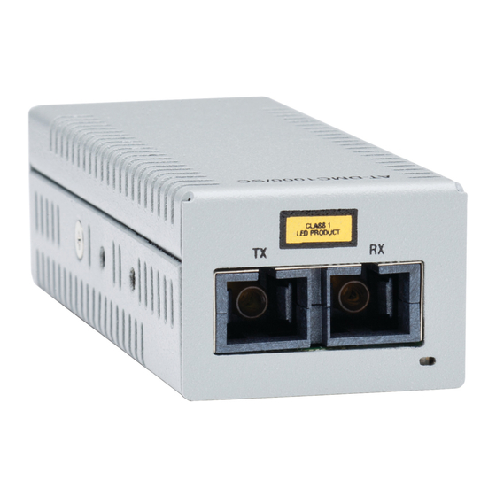
AT-DMC1000/100 Series Desktop Mini Media Converter Installation Guide Front and Back Panels Figure 10 illustrates the front panel of the AT-DMC1000/SC and AT-DMC100/SC Media Converters. Fiber SC TX & RX Ports Fiber Port LINK/ACT LED Figure 10. AT-DMC1000/SC and AT-DMC100/SC Front Panel Figure 11 illustrates the front panel of the AT-DMC1000/ST and AT-DMC100/ST Media Converters. -
Page 26: Figure 12: At-Dmc1000/Lc And At-Dmc100/Lc Front Panel
Chapter 1: Overview Figure 12 illustrates the front panel of the AT-DMC1000/LC and AT-DMC100/LC Media Converters. Fiber LC TX & RX Ports Fiber Port LINK/ACT LED Figure 12. AT-DMC1000/LC and AT-DMC100/LC Front Panel Figure 13 illustrates the media converter back panel. DUP/COL LED Base-T Copper Port... -
Page 27: Figure 14: Media Converter Bottom Panel
AT-DMC1000/100 Series Desktop Mini Media Converter Installation Guide Figure 14 illustrates the media converter bottom panel. SML ON/OFF DIP Switch Figure 14. Media Converter Bottom Panel... -
Page 28: Twisted-Pair Port
Chapter 1: Overview Twisted-Pair Port The twisted-pair (copper) port features an eight-pin RJ45 connector that uses four pins at 100 Mbps and all eight pins at 1000 Mbps. For the port pinouts, see “RJ45 Connector and Port Pinouts” on page 56. The port has a maximum operating distance of 100 meters (328 feet). -
Page 29: Reset The Media Converter
AT-DMC1000/100 Series Desktop Mini Media Converter Installation Guide Reset the Media Converter Reset the media converter by powering the unit OFF, then ON. - Page 30 Chapter 1: Overview...
-
Page 31: Chapter 2 : Installation
Chapter 2 Installation This chapter contains the following sections: “Reviewing Safety Precautions” on page 32 “Selecting a Site for the Media Converter” on page 34 “Planning the Installation” on page 35 “Unpacking the Media Converter” on page 36 ... -
Page 32: Reviewing Safety Precautions
Note indicates that a translation of the safety statement is available in a PDF document titled Translated Safety Statements on the Allied Telesis website at www.alliedtelesis.com/support. Warning Do not stare into the laser beam. Warning Do not look directly at the fiber-optic cable ends or inspect the cable ends with an optical lens. - Page 33 AT-DMC1000/100 Series Desktop Mini Media Converter Installation Guide Note The power input must be provided from SELV source only, per IEC60950. Do not connect to a centralized DC battery bank. Caution Failing to pick up the ferrule tip when you reach the bottom of the cleaning surface can result in static electricity that can damage the fiber-optic cable.
-
Page 34: Selecting A Site For The Media Converter
Chapter 2: Installation Selecting a Site for the Media Converter Observe the following requirements when choosing a site for your media converter: If you are installing the media converter on a table, verify that the table is level and secure. The power outlet for the media converter should be located near ... -
Page 35: Planning The Installation
AT-DMC1000/100 Series Desktop Mini Media Converter Installation Guide Planning the Installation Be sure to observe the following guidelines when planning the installation of your media converter. For AT-DMC1000 media converters, the end node connected to the fiber connector on the media converter must operate at 1000 Mbps. -
Page 36: Unpacking The Media Converter
3. In addition to the media converter, verify that the shipping container includes the following items as follows: Figure 15 on page 37 shows shipping container items for the AT-DMC1000/SC and AT-DMC100/SC. Figure 16 on page 37 shows shipping container items for the AT-DMC1000/ST and AT-DMC100/ST. -
Page 37: Figure 15: At-Dmc1000/Sc And At-Dmc100/Sc Shipping Package Contents
AT-DMC1000/100 Series Desktop Mini Media Converter Installation Guide One USB cable One power adapter (depending on customer order) One fiber port dust covers (pre-installed) Figure 15. AT-DMC1000/SC and AT-DMC100/SC Shipping Package Contents One USB cable One power adapter (depending on customer order) Two fiber port dust covers (pre-installed) Figure 16. -
Page 38: Figure 17: At-Dmc1000/Lc And At-Dmc100/Lc Shipping Package Contents
Chapter 2: Installation One USB cable One power adapter (depending on customer order) One fiber port dust covers (pre-installed) Figure 17. AT-DMC1000/LC and AT-DMC100/LC Shipping Package Contents... -
Page 39: Figure 18: Wall-Mount Kit Shipping Package Contents
AT-DMC1000/100 Series Desktop Mini Media Converter Installation Guide One wall bracket 1 bracket screw for mounting unit to mounting bracket 2 screws for mounting bracket to wall 2 anchors for mounting bracket to wall 2 cable ties Figure 18. Wall-Mount Kit Shipping Package Contents... -
Page 40: Installing The Media Converter On A Desktop
Chapter 2: Installation Installing the Media Converter on a Desktop You may install the media converter on a desktop or on a wall. To install the media converter on a wall, see “Installing the Media Converter on a Wall” on page 41. To install the media converter on a desktop, perform the following procedure: 1. -
Page 41: Installing The Media Converter On A Wall
AT-DMC1000/100 Series Desktop Mini Media Converter Installation Guide Installing the Media Converter on a Wall To install the media converter on a wall, perform the following procedure: 1. Place the media converter on a table. 2. Use a pencil or pen to mark the wall with the locations of the two anchor holes in the mounting bracket (separately purchased). -
Page 42: Figure 20: Securing The Mounting Bracket To The Wall
Chapter 2: Installation Figure 20. Securing the Mounting Bracket to the Wall 5. Slide the media converter through the mounting bracket with the DIP switch facing outward, as shown in Figure 21 on page 43, and secure the bracket to the media converter with the bracket screw included with the bracket. -
Page 43: Figure 21: Attaching The Media Converter To The Mounting Bracket
AT-DMC1000/100 Series Desktop Mini Media Converter Installation Guide Figure 21. Attaching the Media Converter to the Mounting Bracket 6. Go to “Powering On and Cabling the Media Converter” on page 44. -
Page 44: Powering On And Cabling The Media Converter
Chapter 2: Installation Powering On and Cabling the Media Converter Cabling Observe the following guidelines when connecting twisted-pair and fiber- optic cables to the ports on the media converter: Guidelines The connector on the cable should fit snugly into the port on the ... -
Page 45: Figure 22: Securing The Usb Cable Tie
AT-DMC1000/100 Series Desktop Mini Media Converter Installation Guide Figure 22. Securing the USB Cable Tie 3. Do one of the following: Attach the other end of the USB cable to the USB port on a PC, as shown in Figure 23 on page 46. -
Page 46: Figure 23: Connecting Power Via Usb Port
Chapter 2: Installation Figure 23. Connecting Power via USB Port Attach the other end of the USB cable to the USB port on the power adapter, then plug the power adapter to a power outlet, as shown in Figure 24 on page 47. Refer to “Power Specifications” on page 56 for power requirements. -
Page 47: Figure 24: Connecting Power Via Power Adapter
AT-DMC1000/100 Series Desktop Mini Media Converter Installation Guide Figure 24. Connecting Power via Power Adapter 4. Verify that the SYS LED is lit green. If the SYS LED is off, refer to “Troubleshooting” on page 51. 5. Remove the dust cover from the fiber-optic connector(s) and connect the cable to the fiber-optic port as shown in Figure 25 on page 48. -
Page 48: Figure 25: Connecting Cable To Fiber Optic Port
Chapter 2: Installation Figure 25. Connecting Cable to Fiber Optic Port Verify that the media converter’s transmitter port (TX) is connected to the end node’s receiver port (RX) and that the media converter’s receiver port (RX) is connected to the end node’s transmitter port (TX). For example, on the AT-DMC1000/ST media converter, connect the red TX connector on the fiber-optic cable to the transmitter port on the AT-DMC1000/ST media converter and connect the other connector to... -
Page 49: Figure 26: Securing The Fiber Optic Cable Tie
AT-DMC1000/100 Series Desktop Mini Media Converter Installation Guide 6. Secure the fiber optic cable to the media converter using the other cable tie as described below and shown in Figure 26: a. Insert the cable tie through the other integral notch on the mounting bracket. - Page 50 Chapter 2: Installation...
-
Page 51: Chapter 3 : Troubleshooting
This chapter contains information on how to troubleshoot the media converter if a problem occurs. Note For further assistance, please contact Allied Telesis Technical Support at www.alliedtelesis.com/support. Problem 1: The SYS LED on the media converter is off. Solutions: The unit is not receiving power. Try the following: Verify that the power cord is securely connected to the power ... - Page 52 Chapter 3: Troubleshooting Verify that the port is connected to the correct twisted-pair cable. This is to eliminate the possibility that the port is connected to the wrong end-node, such as a powered-off device. Try connecting another end node to the twisted-pair port with a ...
- Page 53 AT-DMC1000/100 Series Desktop Mini Media Converter Installation Guide Test the attenuation on the fiber-optic cable with a fiber-optic tester to determine whether the optical signal is too weak (sensitivity) or too strong (maximum input power). Problem 5: Network performance between the twisted-pair port on the media converter and an end node is slow.
- Page 54 Chapter 3: Troubleshooting...
-
Page 55: Appendix A: Technical Specifications
Appendix A Technical Specifications Below are the technical specifications for the media converters. The specification categories are as follows: “Physical Specifications” “Environmental Specifications” “Power Specifications” on page 56 “Safety and Electromagnetic Emissions Certifications” on page 56 “RJ45 Connector and Port Pinouts”... -
Page 56: Power Specifications
Appendix A: Technical Specifications Power Specifications The following specifications apply to the DC power connector on the media converter. Table 4. Power Specifications Input supply voltage 5 VDC Input current 0.5 A Safety and Electromagnetic Emissions Certifications Table 5. Safety and Electromagnetic Emissions Certifications Safety UL60950-1, EN60950-1 FCC Class A, CISPR 22 Class A,... -
Page 57: Table 6. Mdi Pin Signals (100 Mbps)
AT-DMC1000/100 Series Desktop Mini Media Converter Installation Guide Table 6 lists the pin signals when a port is operating in the MDI configuration at 100 Mbps. Table 6. MDI Pin Signals (100 Mbps) Signal Table 7 lists the pin signals when a port is operating in the MDI-X configuration at 100 Mbps. -
Page 58: Fiber-Optic Port Specifications
Appendix A: Technical Specifications Fiber-Optic Port Specifications The fiber type for the media converter is multimode. Table 9 lists fiber-optic port specifications for the AT-DMC1000 media converters. Table 9. AT-DMC1000 Fiber-Optic Port Specifications Launch Power Fiber Receive Power (dBm) Optic Optical Max. -
Page 59: Appendix B: Cleaning Fiber-Optic Connectors
Appendix B Cleaning Fiber-Optic Connectors This appendix contains the following sections: “Introduction” “Using a Cartridge-Type Cleaner” on page 60 “Using a Swab” on page 62 This appendix describes how to clean fiber-optic connectors. Introduction The fiber-optic connector consists of a fiber-optic plug and its adapter. The end of the fiber-optic cable is held in the core of the ferrule in the plug. -
Page 60: Using A Cartridge-Type Cleaner
Appendix B: Cleaning Fiber-Optic Connectors The end face of an unclean and clean ferrule are shown in Figure 29. Unclean Clean Figure 29. Unclean and Clean Ferrule Using a Cartridge-Type Cleaner Fiber-optic cartridge cleaners, shown in Figure 30, are available from many vendors and are typically called “cartridge cleaners”. -
Page 61: Figure 31: Rubbing The Ferrule Tip On The Cleaning Surface
AT-DMC1000/100 Series Desktop Mini Media Converter Installation Guide Figure 31. Rubbing the Ferrule Tip on the Cleaning Surface Note Rub the ferrule tip on the cleaning surface in one direction only. 3. When you reach the end of the cleaning surface, pick up the ferrule tip, rotate and place it at the top, and rub downwards at least two times. -
Page 62: Using A Swab
Appendix B: Cleaning Fiber-Optic Connectors Warning Do not look directly at the fiber-optic cable ends or inspect the cable ends with an optical lens. Using a Swab Specially treated swabs, or stick cleaners, are available for cleaning inside connector adapters or hard-to-reach ferrule tips. These swabs, often referred to as “lint-free”... -
Page 63: Figure 33: Cleaning A Recessed Ferrule
AT-DMC1000/100 Series Desktop Mini Media Converter Installation Guide To clean a recessed ferrule using a swab, perform the following procedure. 1. Insert the swab into the adapter as shown in Figure 33. Rub the ferrule tip with the swab. Figure 33. Cleaning a Recessed Ferrule 2. - Page 64 Appendix B: Cleaning Fiber-Optic Connectors...
Need help?
Do you have a question about the AT-DMC1000/SC and is the answer not in the manual?
Questions and answers