
Subscribe to Our Youtube Channel
Related Manuals for Allied Telesis AT-MMC6005


Summary of Contents for Allied Telesis AT-MMC6005
-
Page 1: Installation Guide
AT-MMC6000 Series VDSL Mini Media Converters AT-MMC6005 AT-MMC6005-E AT-MMC6006 Installation Guide 613-002395 Rev. A... - Page 2 Allied Telesis, Inc. has been advised of, known, or should have known, the...
-
Page 3: Electrical Safety And Emissions Standards
This product meets the following standards: Federal Communications Commission Interference Statement Declaration of Conformity Manufacturer Name: Allied Telesis, Inc. Declares that the product: VDSL Mini Media Converter Model Number: AT-MMC6000 Series This device complies with Part 15 of the FCC Rules. Operation is subject to the following two conditions: (1) This device may not cause harmful interference, and (2) this device must accept any interference received, including interference that may cause undesired operation. - Page 4 European Union Restriction of the Use of Certain Hazardous Substances (RoHS) in Electrical and Electronic Equipment This Allied Telesis RoHS-compliant product conforms to the European Union Restriction of the Use of Certain Hazardous Substances (RoHS) in Electrical and Electronic Equipment. Allied Telesis ensures RoHS conformance by requiring supplier Declarations of Conformity, monitoring incoming materials, and maintaining manufacturing process controls.
- Page 5 Electrical Safety EN60950-1 (TUV), UL 60950-1 ( Warning Laser Safety: EN60825 Translated Safety Statements Important: The indicates that a translation of the safety statement is available in a PDF document titled Translated Safety Statements on the Allied Telesis website at www.alliedtelesis.com/ support.
-
Page 7: Table Of Contents
Contents Preface................................13 Document Conventions..........................14 Contacting Allied Telesis..........................15 Chapter 1 : Product Description ........................17 Introduction ..............................18 Summary of Features..........................19 Overview ..............................20 Location of Components ..........................21 Feature Description............................ 22 VDSL Line Port............................ 22 VDSL2 Profiles and Settings ....................... 23 10/100/1000 Mbps Twisted Pair Ethernet Port.................. - Page 8 Contents Appendix A: Technical Specifications ......................51 Physical Specifications ..........................51 Environmental Specifications ........................51 Power Specifications ..........................52 Safety and Electromagnetic Emissions Certifications ................52 RJ45 Connector and Port Pinouts ......................53 Appendix B: AT-MMCWLMT Kit Installation ....................55...
- Page 9 Figures Figure 1: Media Converter System Topology ........................20 Figure 2: AT-MMC6005 Front Panel..........................21 Figure 3: AT-MMC6006 Front Panel..........................21 Figure 4: AT-MMC6000 Series Rear Panel ........................21 Figure 5: DIP Switch 1: Subscriber / Provider Unit Configuration..................29 Figure 6: DIP Switches 2, 3, 4: VDSL2 Profile Configuration (Provider Only) ..............
- Page 10 List of Figures...
- Page 11 Table 6: Cables .............................. 37 Table 7: AT-MMC6000 Series Accessory Kit ....................38 Table 8: Physical Specifications ........................51 Table 9: Environmental Specifications - AT-MMC6005 and AT-MMC6006 ........... 51 Table 10: Environmental Specifications - AT-MMC6005-E ................52 Table 11: Power Specifications ........................52 Table 12: Safety and Electromagnetic Emissions Certifications ..............
- Page 12 List of Tables...
-
Page 13: Preface
Preface This preface contains the following sections: “Document Conventions” on page 14 “Contacting Allied Telesis” on page 15 This guide contains instructions on how to install and configure the AT-MMC6000 Series Media Converters. -
Page 14: Document Conventions
Document Conventions This document uses the following conventions: Note Notes provide additional information. Caution Cautions inform you that performing or omitting a specific action may result in equipment damage or loss of data. Warning Warnings inform you that performing or omitting a specific action may result in bodily injury. -
Page 15: Contacting Allied Telesis
AT-MMC6000 Series Installation Guide Contacting Allied Telesis If you need assistance with this product, you may contact Allied Telesis technical support by going to the Support & Services section of the Allied Telesis web site at www.alliedtelesis.com/support. You can find links for the following services on this page: ... -
Page 17: Product Description
Chapter 1 Product Description This chapter describes the following media converters: AT-MMC6005 AT-MMC6005-E AT-MMC6006 This chapter contains the following sections: “Introduction” on page 18 “Summary of Features” on page 19 “Overview” on page 20 ... -
Page 18: Introduction
Refer to Appendix A, ”Technical Specifications” on page 51 for temperature ratings. The difference between the AT-MMC6005 and the AT-MMC6006 models is the VDSL interface: RJ11 phone line connector for the AT-MMC6005 and a BNC coax connector for the AT-MMC6006. Note... -
Page 19: Summary Of Features
AT-MMC6000 Series Installation Guide Summary of Features Very-high-bit-rate digital subscriber line (VDSL2) Line port with: One RJ11 connector for the AT-MMC6005 One BNC connector for the AT-MMC6006 10/100/1000 Mbps Ethernet port with one RJ45 connector Auto-Negotiation and Auto MDI/MDI-X on Ethernet port ... -
Page 20: Overview
Product Description Overview The AT-MMC6000 Series VDSL Mini Media Converter can be used in multi-dwelling units (MDU), multi-tenant buildings (MTU), and in the hospitality industry, such as airports, hotels, and convention centers. This product is designed to operate in pairs of the same model with one of the units configured as the Subscriber and the other unit configured as the Provider. -
Page 21: Location Of Components
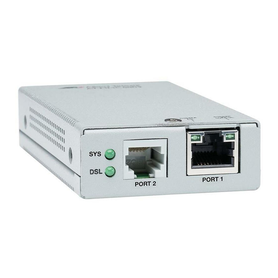
AT-MMC6000 Series Installation Guide Location of Components Figure 2 illustrates the front panel of the AT-MMC6005. Ethernet Port Duplex/Collision Ethernet Port L/A LED System LED DSL LED VDSL2 Line Port Ethernet Port Figure 2. AT-MMC6005 Front Panel Figure 3 illustrates the front panel of the AT-MMC6006. -
Page 22: Feature Description
The port transmits data at frequencies of up to 30 MHz. This port features an RJ11 telephone connector on the AT-MMC6005 or a BNC coax connector on the AT-MMC6006. Table 1 lists the pinouts and their assignments on the AT-MMC6005 RJ11 VDSL port. Table 1. AT-MMC6005 RJ11 VDSL Port... -
Page 23: Vdsl2 Profiles And Settings
AT-MMC6000 Series Installation Guide VDSL2 Profiles The AT-MMC6000 Series Media Converter supports all VDSL2 profiles defined by ITU-T G.993.2. When the media converter is in CO (Provider) and Settings mode, the user is allowed to select from a predetermined list of profiles (see Table 2 on page 24 and Table 3 on page 25 for details). -
Page 24: Table 2: Vdsl2 Dip Switch Settings - Profiles, Description, Usage
Product Description Table 2. VDSL2 DIP Switch Settings - Profiles, Description, Usage DIP Switch Profile Description Usage Medium loops Medium distance applications where more data is expected to flow in a particular direction Down Short loops, high Short distance applications where data is data rates expected to flow equally in both directions... -
Page 25: Table 3: Vdsl2 Dip Switch Settings - Additional Information
AT-MMC6000 Series Installation Guide Table 3. VDSL2 DIP Switch Settings - Additional Information DIP Switch Max Data Rate Bandwidth (Mbps) Symmetric/ Data Loop G.inp (MHz) Downstream/ Asymmetric Interleaving Length* Upstream** <2.5 km 90/40 Asymmetric (8k ft) Down <1 km 150/150 Symmetric (35k ft) Down... -
Page 26: 10/100/1000 Mbps Twisted Pair Ethernet Port
Product Description 10/100/1000 Each of the AT-MMC6000 Series media converters have one twisted pair Ethernet port. The twisted pair port features RJ45 connectors with a Mbps Twisted maximum operating distance of 100 meters (328 feet). For the port pinout Pair Ethernet details, refer to “RJ45 Connector and Port Pinouts”... -
Page 27: Half- And Full-Duplex Mode
AT-MMC6000 Series Installation Guide Half- and Full-duplex Mode Duplex mode refers to the way an end-node sends and receives data on the network. An end-node can operate in either half- or full-duplex mode, depending on its capabilities. An end-node that is operating in half-duplex mode can either send data or receive data, but it cannot do both at the same time. - Page 28 Product Description Table 5. Status LEDs (Continued) State Description Slow Blinking VDSL is idle when blinking occurs Green approximately once per second. Fast Blinking VDSL is in Training or Handshaking Green mode when blinking occurs approximately 3 times per second. Steady Green VDSL has established connection with its link partner.
-
Page 29: Dip Switches
AT-MMC6000 Series Installation Guide Table 5. Status LEDs (Continued) State Description The port has not established a link or the link is in Half-Duplex mode. Steady Green The port has established a link in Full- Duplex mode. COPPER Rapid Collisions are occurring on the port. P1 DUP/ Blinking Green... -
Page 30: Vdsl2 Configuration
Product Description VDSL2 Configuration DIP switches 2, 3, and 4 configure the media converter VDSL2 profile on the Provider unit. For the supported VDSL2 settings, refer to Table 2 on page 24 and Table 3 on page 25. VDSL Switches Figure 6. -
Page 31: Smart Missinglink™ (Sml)
AT-MMC6000 Series Installation Guide Smart SML Overview MissingLink™ If an Ethernet connection to one of the media converters loses link, the (SML) Smart MissingLink™ (SML) feature allows you to determine which port still has a valid Ethernet connection and which port requires troubleshooting. The value to this type of network monitoring and fault notification is that you can quickly determine which media converter’s port has failed and pinpoint the specific area where the problem is occurring. -
Page 32: Dc Power Supply Input Port
The power adapter supplies 12VDC to Power Adapter the media converter. Allied Telesis supplies an approved safety compliant AC power adapter specifically designed for each region in which the media converter is sold. Each type of power adapter has a regulated... -
Page 33: Installation
Chapter 2 Installation This chapter contains the installation procedures for the media converters. The installation process is described in the following sections: “Installation Safety Precautions” on page 34 “Selecting a Site for the Media Converter” on page 36 ... -
Page 34: Installation Safety Precautions
Caution Operating Temperature. The AT-MMC6006-E product is designed for a maximum ambient temperature of 65 degrees C. Caution Operating Temperature. The AT-MMC6005 and AT-MMC6006 products are designed for a maximum ambient temperature of 50 degrees C. - Page 35 Please use caution when operating the product at these ambient temperatures. Caution Only use the power adapter supplied with the device. E102 The following applies to the AT-MMC6005-E: Warning This equipment shall be installed in a Restricted Access location. ...
-
Page 36: Selecting A Site For The Media Converter
Installation Selecting a Site for the Media Converter The AT-MMC6000 Series Media Converter may be individually installed on a desk top, mounted on a wall or rack mounted. When mounting the unit to a wall, you must use the AT-MMCWLMT Kit which is not included with the AT-MMC6000 Series Media Converter. -
Page 37: Cables Not Included
Table 6. Cables Port Cable Connector Ethernet Category 5 or better RJ45 All AT-MMC6000 Series models 100-ohm unshielded straight-through or crossover twisted pair cable VDSL Line Standard telephone RJ11 AT-MMC6005 Series models cable VDSL Line Standard coax cable. AT-MMC6006 Series models... -
Page 38: Unpacking The Media Converter
1. Remove all components from the shipping package and store the packaging material in a safe location. Note Allied Telesis recommends that you store the packaging in case you need to return the unit for service. 2. Place the media converter on a level, secure surface. -
Page 39: Installing The Subscriber Unit
AT-MMC6000 Series Installation Guide Installing the Subscriber Unit The Subscriber unit will be used as a stand-alone device, and can be installed on a desktop, or mounted onto a wall, using wall-mounting brackets that are provided separately. The Subscriber unit and the Provider unit must be the same model of the AT-MMC6000 Series. -
Page 40: Setting The Subscriber Unit Dip Switches
Installation Setting the 1. Set DIP switch 1 to the Up (CPE) position as shown in Figure 11. This configures the media converter as a Subscriber unit. Subscriber Unit DIP Switches Subscriber (Up position) Figure 11. Subscriber Unit DIP Switch Position 2. -
Page 41: Figure 12: Subscriber Unit Ethernet Port To Computer
2. Connect the DSL port on the Subscriber unit to the VDSL wall jack or the interior VDSL line in the building with either a phone line for the AT-MMC6005 or a coax cable for the AT-MMC6006 as shown in Figure 13. This connection allows the Subscriber unit to communicate directly with the Provider unit. -
Page 42: Powering On The Subscriber Unit
Installation Powering On the To apply power to the Subscriber unit, perform the following: Subscriber Unit 1. Plug the DC connector of the external power adapter to the power receptacle connector labeled 12VDC on the back panel of the unit and turn the cord clockwise one-quarter turn to lock, as shown in Figure 14 on page 42. -
Page 43: Installing The Provider Unit
Refer to the AT-MMCR18 Chassis Installation Guide for installation instructions. Note The Subscriber unit and the Provider unit must be the same model of the AT-MMC6000 Series. Warning The AT-MMC6005-E equipment shall be installed in a Restricted Access location. -
Page 44: Using The Provider Unit On A Desktop
Installation Using the To use the Provider unit on a desktop, perform the following procedure: Provider Unit on 1. Position the Provider unit upside down and attach the rubber feet a Desktop provided to the bottom of the unit as shown in Figure 10. Figure 15. -
Page 45: Setting The Provider Unit Dip Switches
AT-MMC6000 Series Installation Guide Note Set the DIP switches before the media converter is installed in the AT-MMCR18 chassis because the switches are hidden afterward. 2. Refer to the AT-MMCR18 Chassis Installation Guide for installation instructions. 3. Go to “Cabling the Provider Unit” on page 47. Setting the 1. - Page 46 Installation 4. If you are mounting your media converter on a desktop or a wall, go to “Cabling the Provider Unit” on page 47. If you are installing your media converter in an AT-MMCR18 chassis to be rack mounted, go to step 2 of “Rack Mounting the Provider Unit” on page 44.
-
Page 47: Cabling The Provider Unit
2. Connect the VDSL Line port on the Provider unit to the VDSL wall jack or the building VDSL line in the building with either a phone line for the AT-MMC6005 or a coax cable for the AT-MMC6006 as shown in Figure 18. This connection allows the Provider unit to communicate directly with the Subscriber unit. -
Page 48: Powering On The Provider Unit
Installation Powering On the To apply power to the Provider unit, perform the following: Provider Unit 1. Plug the DC of the external power adapter to the power receptacle connector labeled 12VDC on the back panel of the unit and turn the cord clockwise one-quarter turn to lock, as shown in Figure 14 on page Figure 19. -
Page 49: Chapter 3 : Troubleshooting
This chapter contains information on how to troubleshoot the AT-MMC6000 Series media converters in the event a problem occurs. Note For further assistance, please contact Allied Telesis Technical Support at www.alliedtelesis.com/support. Problem 1: The SYS LED on the media converter is off. - Page 50 Troubleshooting Verify that the twisted-pair cable is securely connected to the port on the media converter channel and to the port on the remote end- node. Verify that the port is connected to the correct twisted-pair cable. This is to eliminate the possibility that the port is connected to the wrong end-node, such as a powered-off device.
-
Page 51: Appendix A: Technical Specifications
(2.0 in x 3.9 in x 0.8 in) Weight 0.2 kg (0.4 lb) Environmental Specifications Table 9 lists environmental specifications for the AT-MMC6005 and AT-MMC6006. Table 9. Environmental Specifications - AT-MMC6005 and AT-MMC6006 Operating Temperature 0° C to 50° C (32° F to 122° F) Storage Temperature -30°... -
Page 52: Power Specifications
Technical Specifications Table 10 lists environmental specifications for the AT-MMC6005-E. Table 10. Environmental Specifications - AT-MMC6005-E Operating Temperature -20° C to 65° C (-4° F to 149° F) Storage Temperature -40° C to 80° C (-40° F to 176° F) -
Page 53: Rj45 Connector And Port Pinouts
AT-MMC6000 Series Installation Guide RJ45 Connector and Port Pinouts Figure 20 illustrates the pin layout for the RJ45 connector and port. Figure 20. RJ45 Connector and Port Pin Layout Table 13 lists the pin signals when a port is operating in the MDI configuration at 10 or 100 Mbps. -
Page 54: Table 15: Pin Signals (1000 Mbps)
Technical Specifications Table 15 lists the pin signals when a port is operating at 1000 Mbps. Table 15. Pin Signals (1000 Mbps) Signal Pair Name TX+_D1 TX-_D1 RX+_D2 BI+_D3 BI-_D5 RX-_D2 BI+_D4 BI-_D4... -
Page 55: Appendix B: At-Mmcwlmt Kit Installation
Appendix B AT-MMCWLMT Kit Installation Before installing an MMC media converter on a wall, you must have an AT-MMCWLMT Kit that is provided separately. 1. Verify that the AT-MMCWLMT Kit contains the items shown in Table 16. Table 16 AT-MMCR WLMT Kit Contents Description Illustration Ten Wall... -
Page 56: Figure 21: Attaching The Brackets To The Media Converter
AT-MMCWLMT Kit Installation 4. Orient the brackets against the sides of the unit, as shown in Figure 21, and secure them to the unit with the four of the brackets screws included. Figure 21. Attaching the Brackets to the Media Converter 5. -
Page 57: Figure 23: Securing The Media Converter To The Wall
AT-MMC6000 Series Installation Guide 7. Secure the Subscriber unit to the wall using four wall-mounting screws. See Figure 23. Figure 23. Securing the Media Converter to the Wall... - Page 58 AT-MMCWLMT Kit Installation...
Need help?
Do you have a question about the AT-MMC6005 and is the answer not in the manual?
Questions and answers