
Related Manuals for Allied Telesis AT-PC2000/LC


Summary of Contents for Allied Telesis AT-PC2000/LC
-
Page 1: Installation Guide
PC2000/200 Series PoE+ Switching Media Converters AT-PC2000/SC AT-PC2000/LC AT-PC2000/SP AT-PC200/SC Installation Guide 613-002346 Rev A... - Page 2 Allied Telesis, Inc. has been advised of, known, or should have known, the...
-
Page 3: Industry Canada
Electrical Safety and Emissions Standards This section contains the following: “US Federal Communications Commission” “Industry Canada” “Emissions, Immunity and Electrical Safety Standards” on page 4 “Translated Safety Statements” on page 4 US Federal Communications Commission Radiated Energy Note This equipment has been tested and found to comply with the limits for a Class A digital device pursuant to Part 15 of FCC Rules. - Page 4 Electrical Safety EN60950-1 (TUV), UL 60950-1 ( Warning Laser Safety: EN60825 Translated Safety Statements Important: The indicates that a translation of the safety statement is available in a PDF document titled Translated Safety Statements on the Allied Telesis website at www.alliedtelesis.com/support.
-
Page 5: Table Of Contents
Symbol Conventions ..........................12 Contacting Allied Telesis..........................13 Chapter 1 : Overview ............................. 15 Introduction ..............................16 Features ..............................17 AT-PC2000/SC and AT-PC2000/LC ..................... 17 AT-PC2000/SP..........................17 AT-PC200/SC ..........................17 Twisted-Pair Port ..........................18 Power over Ethernet..........................18 Fiber Connection ..........................19 Auto MDI/MDI-X .......................... - Page 6 Contents Introduction..............................57 Using a Cartridge-Type Cleaner......................... 58 Using a Swab ............................. 60...
- Page 7 Figure 8: SML with Fiber Connection Between Media Converters Down................24 Figure 9: Enabling SML ............................... 24 Figure 10: AT-PC2000/SC and AT-PC200/SC Front Panel Features ................. 25 Figure 11: AT-PC2000/LC Front Panel Features ........................ 25 Figure 12: AT-PC2000/SP Front Panel Features ........................ 26 Figure 13: Media Converter Back Panel..........................26 Figure 14: AT-PC2000/SC and AT-PC200/SC Shipping Package Contents...............
- Page 8 List of Figures...
- Page 9 Tables Table 1. Media Converter LED Functional Descriptions .....................20 Table 2. Twisted-Pair Port Cabling Specifications ......................34 Table 3. Copper Connection Speed/Duplex Settings and Resulting Speed - AT-PC2000 ..........35 Table 4. Copper Connection Speed/Duplex Settings and Resulting Speed - AT-PC200 ...........36 Table 5.
- Page 10 List of Tables...
-
Page 11: Preface
Preface This preface contains the following sections: “Symbol Conventions” on page 12 “Contacting Allied Telesis” on page 13 This guide contains the installation instructions for the following PoE+ Switching Media Converters. AT-PC2000/SC AT-PC2000/SP AT-PC2000/LC AT-PC200/SC... -
Page 12: Symbol Conventions
Symbol Conventions This document uses the following conventions: Note Notes provide additional information. Caution Cautions inform you that performing or omitting a specific action may result in equipment damage or loss of data. Warning Warnings inform you that performing or omitting a specific action may result in bodily injury. -
Page 13: Contacting Allied Telesis
PC2000/200 Series Switching Media Converter Installation Guide Contacting Allied Telesis If you need assistance with this product, you may contact Allied Telesis technical support by going to the Support & Services section of the Allied Telesis web site at www.alliedtelesis.com/support. You can find links for... -
Page 15: Chapter 1 : Overview
“Features” on page 17 “Front and Back Panels” on page 25 “Twisted-Pair Port” on page 27 “Reset the Media Converter” on page 28 This chapter describes the following Switching Media Converters: AT-PC2000/SC AT-PC2000/SP AT-PC2000/LC AT-PC200/SC ... -
Page 16: Introduction
100Mbps fiber networks. Operate at 1000Mbps full duplex (AT-PC2000/SC and AT-PC2000/LC), 100/1000 Mbps full duplex (AT-PC2000/SP, depending on the SFP type), or 100Mbps full duplex (AT-PC200/ SC). Can be installed on a desktop or can be wall mounted: easy to ... -
Page 17: Features
PC2000/200 Series Switching Media Converter Installation Guide Features Here are the key features of the PC2000/200 Series converters: AT-PC2000/SC and AT-PC2000/LC 1000Base-SX fiber-optic port PoE+ via twisted-pair port Auto Negotiation or fixed 100Mpbs full duplex and Auto MDI/MDI-X ... -
Page 18: Twisted-Pair Port
PoE device. 35W internal AC power supply Twisted-Pair Port Here are the basic features of the twisted-pair (copper) port: 10/100/1000 Mbps (AT-PC2000/SC, AT-PC2000/LC, AT-PC2000/ SP) or 10/100 Mbps (AT-PC200/SC) 10/100/1000Base-T compliant (AT-PC2000/SC, AT-PC2000/LC, AT-PC2000/SP) or 10/100Base-T compliant (AT-PC200/SC) IEEE 802.3u Auto-Negotiation compliant... -
Page 19: Fiber Connection
The PC2000/200 Series converters support the following transceiver fiber connections: The AT-PC2000/SC has a fixed dual fiber SC 1000-X connection. The AT-PC2000/LC has a fixed dual fiber LC 1000-X connection. The AT-PC200/SC has a fixed dual fiber SC 100-FX connection. ... -
Page 20: Leds
Chapter 1: Overview LEDs Figure 2 shows the media converter LEDs. Copper PORT 2 Fiber PORT 1 Copper PORT 2 POE FAULT POE POWER Figure 2. LEDs Table 1 describes the media converter’s LEDs. Table 1. Media Converter LED Functional Descriptions State Description The media converter is not operational... - Page 21 PC2000/200 Series Switching Media Converter Installation Guide Table 1. Media Converter LED Functional Descriptions (Continued) State Description The port has not established a link. Steady The port has an established link to a Green network device, but it is not transmitting Copper or receiving network packets.
-
Page 22: Smart Missinglink™ (Sml)
Chapter 1: Overview Smart If one of the Ethernet connections to the media converter loses link, the Smart MissingLink™ (SML) feature allows you to determine which port still MissingLink™ has a valid connection and which port requires troubleshooting. The value (SML) to this type of network monitoring and fault notification is that you can quickly determine which media converter port has failed and troubleshoot... -
Page 23: Sml Example Scenarios With Two Connected Media Converters
PC2000/200 Series Switching Media Converter Installation Guide Figure 5 shows media converter and end node L/A LED behavior with SML enabled with a copper connection down. End Node End Node PC2000/200 Copper Cable Fiber Cable Link LED Off Copper L/A Fiber L/A Link LED Blinking LED Off... -
Page 24: Enabling Sml
Chapter 1: Overview Figure 8 shows media converter and end node L/A LED behavior with SML enabled with a fiber connection down between the PC2000/200 series media converter and the other media converter. PC2000/200 End Node Media Converter End Node Copper L/A Fiber L/A Fiber L/A... -
Page 25: Front And Back Panels
DIP Switches Fiber SC TX & RX PORT 1 Ports L/A LED Figure 10. AT-PC2000/SC and AT-PC200/SC Front Panel Features The front panel features of the AT-PC2000/LC Media Converter are shown in Figure 11. Copper Copper Copper Port PORT 2... -
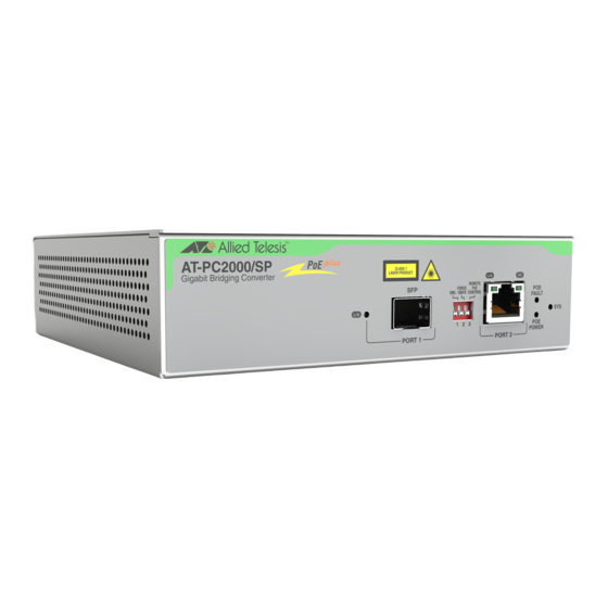
Page 26: Figure 12: At-Pc2000/Sp Front Panel Features
Chapter 1: Overview The front panel features of the AT-PC2000/SP Media Converter are shown in Figure 12. Copper Copper Copper Port PORT 2 PORT 2 D/C LED L/A LED POE FAULT LED SYS LED POE POWER LED Fiber DIP Switches Fiber SP SFP Slot PORT 1 L/A LED... -
Page 27: Twisted-Pair Port
PC2000/200 Series Switching Media Converter Installation Guide Twisted-Pair Port The twisted-pair port features an eight-pin RJ45 connector that uses four pins at 10 or 100 Mbps and all eight pins at 1000 Mbps. For the port pinouts, see “RJ45 Connector and Port Pinouts” on page 54. The port has a maximum operating distance of 100 meters (328 feet). -
Page 28: Reset The Media Converter
Chapter 1: Overview Reset the Media Converter Reset the media converter by powering OFF then powering ON the unit. -
Page 29: Chapter 2 : Installation
Chapter 2 Installation This chapter contains the following sections: “Reviewing Safety Precautions” on page 30 “Selecting a Site for the Media Converter” on page 33 “Planning the Installation” on page 34 “Unpacking the Media Converter” on page 37 ... -
Page 30: Reviewing Safety Precautions
available in a PDF document titled Translated Safety Statements on the Allied Telesis website at www.alliedtelesis.com/support. Warning To prevent electric shock, do not remove the cover. No userserviceable parts inside. This unit contains hazardous voltages and should only be opened by a trained and qualified technician. - Page 31 PC2000/200 Series Switching Media Converter Installation Guide Caution Air vents must not be blocked and must have free access to the room ambient air for cooling. Note All Countries: Install product in accordance with local and National Electrical Codes. ...
- Page 32 Chapter 2: Installation Warning An SFP transceiver can be damaged by static electricity. Be sure to observe all standard electrostatic discharge (ESD) precautions, such as wearing an antistatic wrist strap, to avoid damaging the transceiver. Warning Do not stare into the laser beam. ...
-
Page 33: Selecting A Site For The Media Converter
PC2000/200 Series Switching Media Converter Installation Guide Selecting a Site for the Media Converter Observe the following requirements when choosing a site for your media converter: If you are installing the media converter on a table, verify that the table is level and secure. -
Page 34: Planning The Installation
Chapter 2: Installation Planning the Installation Be sure to observe the following guidelines when planning the installation of your media converter. On the AT-PC2000 media converters, the end node connected to the fiber connector on the media converter must operate at 1000 Mbps, except for the AT-PC2000/SP when using a 100 Mbps SFP module. -
Page 35: Table 3. Copper Connection Speed/Duplex Settings And Resulting Speed - At-Pc2000
PC2000/200 Series Switching Media Converter Installation Guide For speed/duplex interactions between the copper port on the AT-PC2000 and the copper link partner, refer to Table 3 for allowable speed/duplex combinations. Table 3. Copper Connection Speed/Duplex Settings and Resulting Speed - AT-PC2000 AT-PC2000 Copper Port Copper Link Partner Port Setting... -
Page 36: Table 4. Copper Connection Speed/Duplex Settings And Resulting Speed - At-Pc200
Chapter 2: Installation Table 4. Copper Connection Speed/Duplex Settings and Resulting Speed - AT-PC200 AT-PC200 Copper Port Copper Link Partner Port Setting Speed/Duplex Setting Auto Negotiation 100Mbps Force 100Mbps Force 1000Mbps Full Duplex Half Duplex Force Full Duplex* Auto Negotiation 100Mbps full Duplex 100Mbps half... -
Page 37: Unpacking The Media Converter
Figure 14 on page 38 shows shipping container items for the AT-PC2000/SC and AT-PC200/SC. Figure 15 on page 39 shows shipping container items for the AT-PC2000/LC. Figure 16 on page 40 shows shipping container items for the AT-PC2000/SP. -
Page 38: Figure 14: At-Pc2000/Sc And At-Pc200/Sc Shipping Package Contents
Chapter 2: Installation Four wall screws Four rubber feet (for desktop installation) One regional AC power cord One power cord retaining clip One fiber port dust cover (pre- installed) Figure 14. AT-PC2000/SC and AT-PC200/SC Shipping Package Contents... -
Page 39: Figure 15: At-Pc2000/Lc Shipping Package Contents
PC2000/200 Series Switching Media Converter Installation Guide Four wall screws Four rubber feet (for desktop installation) One regional AC power cord One power cord retaining clip One fiber port dust cover (pre- installed) Figure 15. AT-PC2000/LC Shipping Package Contents... -
Page 40: Figure 16: At-Pc2000/Sp Shipping Package Contents
Chapter 2: Installation Four wall screws Four rubber feet (for desktop installation) One regional AC power cord One power cord retaining clip One SFP slot dust cover (pre- installed) Figure 16. AT-PC2000/SP Shipping Package Contents... -
Page 41: Installing The Power Cord Retaining Clip
PC2000/200 Series Switching Media Converter Installation Guide Installing the Power Cord Retaining Clip Perform the following procedure to install the power cord retaining clip on the media converter: 1. Locate the power cord retaining clip, as shown in Figure 17. Figure 17. -
Page 42: Installing The Media Converter On A Desktop
Chapter 2: Installation Installing the Media Converter on a Desktop You may install the media converter on a desktop or on a wall. To install the media converter on a wall, see “Installing the Media Converter on a Wall” on page 43. To install the media converter on a desktop, perform the following procedure: 1. -
Page 43: Installing The Media Converter On A Wall
PC2000/200 Series Switching Media Converter Installation Guide Installing the Media Converter on a Wall To install the media converter on a wall, perform the following procedure: 1. Place the media converter on a table. 2. Install the two wall anchors into the wall so that they are level with each other and are spaced 64 mm (2.52 in) apart. -
Page 44: Installing The Sfp Transceiver
Chapter 2: Installation Installing the SFP Transceiver To install an SFP transceiver, perform the following procedure: Note The transceiver can be hot-swapped; you do not need to power off the media converter to install a transceiver. However, always remove the cable before removing the transceiver. Note You should always install the transceiver before connecting the fiber-optic cable to it. -
Page 45: Figure 21: Inserting The Sfp
PC2000/200 Series Switching Media Converter Installation Guide 4. Slide the transceiver into the SFP slot until it clicks into place. See Figure 21. Figure 21. Inserting the SFP 5. Verify that the handle on the transceiver is in the upright position, as shown in Figure 22. - Page 46 Chapter 2: Installation For information on the cable specifications of the SFP, consult the documentation shipped with the SFP. 6. Go to “Powering On and Cabling the Media Converter” on page 47.
-
Page 47: Powering On And Cabling The Media Converter
PC2000/200 Series Switching Media Converter Installation Guide Powering On and Cabling the Media Converter Cabling Observe the following guidelines when connecting twisted-pair and fiber- optic cables to the ports on the media converter: Guidelines The connector on the cable should fit snugly into the port on the ... - Page 48 Chapter 2: Installation 2. Lower the retaining clip over the AC Power Cord as shown in Figure 23 on page 47. 3. Plug the other end of the power cord into a wall outlet. Warning Power cord is used as a disconnection device. To de-energize equipment, disconnect the power cord.
-
Page 49: Chapter 3 : Troubleshooting
This chapter contains information on how to troubleshoot the media converter if a problem occurs. Note For further assistance, please contact Allied Telesis Technical Support at www.alliedtelesis.com/support. Problem 1: The POE POWER LED on the media converter is off. Solutions: The PoE port on the unit is not supplying power. Try the following: Verify a PoE device is plugged into the port. - Page 50 Chapter 3: Troubleshooting Verify that the end node connected to the twisted-pair port is powered on and is operating properly. Verify that the twisted-pair cable is securely connected to the port on the media converter channel and to the port on the remote end- node.
- Page 51 PC2000/200 Series Switching Media Converter Installation Guide On the AT-PC2000/SP, verify that the operating specifications and wave lengths of the fiber-optic port on the SFP transceiver and the remote end-node are compatible. Verify that the correct type of fiber-optic cabling is being used. ...
- Page 52 Chapter 3: Troubleshooting...
-
Page 53: Appendix A: Technical Specifications
Appendix A Technical Specifications Below are the technical specifications for the media converters. The specification categories are as follows: “Physical Specifications” “Environmental Specifications” “Power Specifications” on page 54 “Safety and Electromagnetic Emissions Certifications” on page 54 “RJ45 Connector and Port Pinouts”... -
Page 54: Power Specifications
Appendix A: Technical Specifications Power Specifications Table 7. Power Specifications Max power consumption 50 W (including PoE power) Input voltage range 100-240 VAC Safety and Electromagnetic Emissions Certifications Table 8. Safety and Electromagnetic Emissions Certifications UL60950-1, EN60950-1, Safety EN60825-1 FCC Class A, CISPR 22 Class A, Emissions (EMI) EN55022 Class A, RCM, VCCI Class A... -
Page 55: Table 9. Mdi Pin Signals (10 Or 100 Mbps)
PC2000/200 Series Switching Media Converter Installation Guide Table 9 lists the pin signals when a port is operating in the MDI configuration at 10 or 100 Mbps. Table 9. MDI Pin Signals (10 or 100 Mbps) Signal Table 10 lists the pin signals when a port is operating in the MDI-X configuration at 10 or 100 Mbps. -
Page 56: Fiber-Optic Port Specifications
Appendix A: Technical Specifications Fiber-Optic Port Specifications The fiber type for the media converter is multimode. Table 12 lists fiber-optic port specifications for the AT-PC2000 media converters. Note Fiber optic port specifications for the AT-PC2000/SP are dependent upon the type of SFP inserted. Table 12. -
Page 57: Appendix B: Cleaning Fiber-Optic Connectors
Appendix B Cleaning Fiber-Optic Connectors This appendix contains the following sections: “Introduction” “Using a Cartridge-Type Cleaner” on page 58 “Using a Swab” on page 60 This appendix describes how to clean fiber-optic connectors. Introduction The fiber-optic connector consists of a fiber-optic plug and its adapter. The end of the fiber-optic cable is held in the core of the ferrule in the plug. -
Page 58: Figure 26: Unclean And Clean Ferrule
Appendix B: Cleaning Fiber-Optic Connectors The end face of an unclean and clean ferrule are shown in Figure 26. Unclean Clean Figure 26. Unclean and Clean Ferrule Using a Cartridge-Type Cleaner Fiber-optic cartridge cleaners, shown in Figure 27, are available from many vendors and are typically called “cartridge cleaners”. -
Page 59: Figure 28: Rubbing The Ferrule Tip On The Cleaning Surface
PC2000/200 Series Switching Media Converter Installation Guide Figure 28. Rubbing the Ferrule Tip on the Cleaning Surface Note Rub the ferrule tip on the cleaning surface in one direction only. 3. When you reach the end of the cleaning surface, pick up the ferrule tip, rotate and place it at the top, and rub downwards at least two times. -
Page 60: Figure 29: Lint-Free And Alcohol-Free Swabs
Appendix B: Cleaning Fiber-Optic Connectors Warning Do not look directly at the fiber-optic cable ends or inspect the cable ends with an optical lens. Using a Swab Specially treated swabs, or stick cleaners, are available for cleaning inside connector adapters or hard-to-reach ferrule tips. These swabs, often referred to as “lint-free”... -
Page 61: Figure 30: Cleaning A Recessed Ferrule
PC2000/200 Series Switching Media Converter Installation Guide To clean a recessed ferrule using a swab, perform the following procedure. 1. Insert the swab into the adapter as shown in Figure 30. Rub the ferrule tip with the swab. Figure 30. Cleaning a Recessed Ferrule 2. - Page 62 Appendix B: Cleaning Fiber-Optic Connectors...
Need help?
Do you have a question about the AT-PC2000/LC and is the answer not in the manual?
Questions and answers