Digi ConnectCore 8X Hardware Reference Manual
Sbc express
Hide thumbs
Also See for ConnectCore 8X:
- Hardware reference manual (116 pages) ,
- Hardware design manuallines and checklist (15 pages) ,
- Hardware reference manual (89 pages)
Table of Contents
Advertisement
Quick Links
Advertisement
Table of Contents

Related Manuals for Digi ConnectCore 8X


Summary of Contents for Digi ConnectCore 8X
- Page 1 ConnectCore 8X SBC Express Hardware Reference Manual -- Preliminary...
- Page 2 Information in this document is subject to change without notice and does not represent a commitment on the part of Digi International. Digi provides this document “as is,” without warranty of any kind, expressed or implied, including, but not limited to, the implied warranties of fitness or merchantability for a particular purpose.
-
Page 3: Table Of Contents
Include the document title and part number (ConnectCore® 8X SBC Express Hardware Reference Manual -- Preliminary, 90002296 2P) in the subject line of your email. Contents About the ConnectCore 8X SBC Express Features and functionality Block diagram Interfaces Connectors, jumpers, and switches... -
Page 4: About The Connectcore 8X Sbc Express
About the ConnectCore 8X SBC Express The ConnectCore 8X SBC Express is an ultra-compact board featuring the Digi ConnectCore 8X system-on-module (SoM). The ConnectCore 8X system-on-module integrates an NXP i.MX 8X application processor with LPDDR4 and eMMC flash memory, WLAN/Bluetooth, power management IC... - Page 5 About the ConnectCore 8X SBC Express Features and functionality User interface: x1 User LED. x1 User button. Dimensions: 87 x 63 mm ConnectCore® 8X SBC Express Hardware Reference Manual -- Preliminary...
-
Page 6: Block Diagram
About the ConnectCore 8X SBC Express Block diagram Block diagram ConnectCore® 8X SBC Express Hardware Reference Manual -- Preliminary... -
Page 7: Interfaces
Interfaces Block diagram Interfaces Connectors, jumpers, and switches Top view Bottom view Description Input power connector Coin cell connector Boot mode Power and reset buttons Console port microSD 10/100Mbps Ethernet LVDS/MIPI-DSI display Touch controller USB host XBee Expansion connector User LED and button ConnectCore®... -
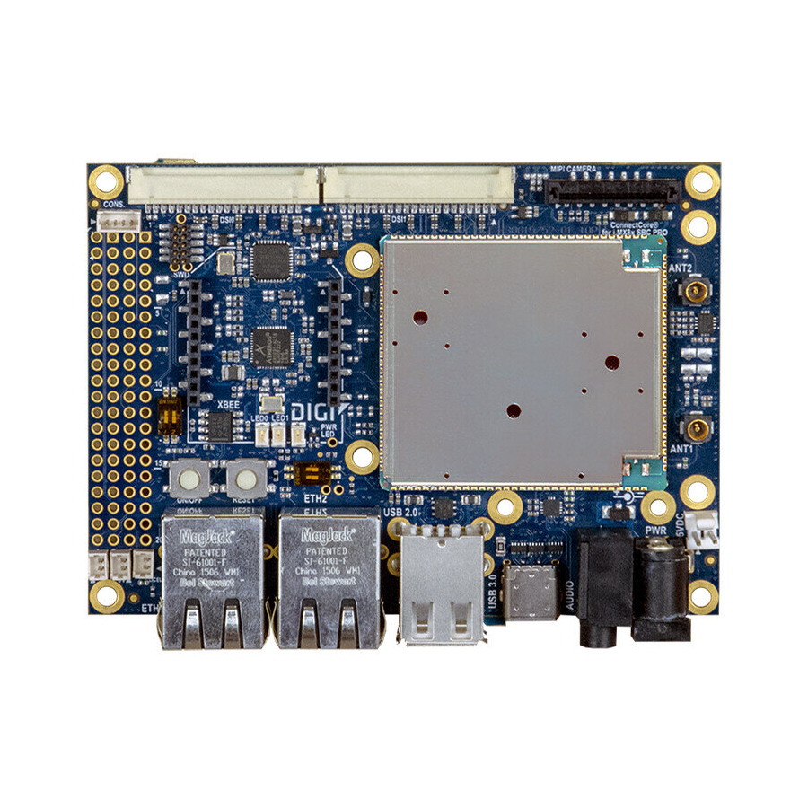
Page 8: Connectors, Jumpers, And Switches
Interfaces Connectors, jumpers, and switches Connectors, jumpers, and switches Top view ConnectCore® 8X SBC Express Hardware Reference Manual -- Preliminary... -
Page 9: Bottom View
Interfaces Bottom view Bottom view Description Connector Interface Manufacturer Manufacturer part number Coin cell Molex 53047-0210 Console Molex 53047-0410 Ethernet XMultiple XMG-9799-8821-100D-L1TO-H- LVDS Hirose DF14A-20P-1.25H MIPI-DSI SFW15S-2STE1LF USB Host KYCON KUSBX-AS2N USB OTG KYCON KMMX-ABSMT5SG-30TR Expansion header Wurth 61304021121 Electronics ConnectCore®... -
Page 10: Input Power Connector
FTSH-105-01-F-DV default) Input power connector A 5V DC-in power jack connector (J2) provides power to the ConnectCore 8X SBC Express system. From this 5V power supply, a 3.3V LDO generates the power supply for the on-module MCA. Coin cell connector A 2-pin, 1.25 mm pitch straight connector (J4), not populated by default, can be used to connect an... -
Page 11: Power And Reset Buttons
For more information about the boot mode configuration, see the ConnectCore 8X System-on-Module Hardware Reference Manual. Power and reset buttons The power button (SW1) on the ConnectCore 8X SBC Express is connected to the on-module MCA, which provides the following functionality: Board status Power button action Response Short press... -
Page 12: Swd
Console port The ConnectCore 8X SBC Express provides a 4-pin, 1.25 mm pitch connector (J5) as its debug console port. The UART2 port of the ConnectCore 8X system-on-module is used for this purpose. The console signal is a serial TTL, which travels through the console connector directly to the i.MX 8X processor. A TTL-to-USB cable can be used for accessing this console port from a host PC USB port. -
Page 13: Microsd
LVDS/MIPI-DSI display One of the two MIPI-DSI/LVDS combo PHYs supported by the ConnectCore 8X system-on-module is available over two different display connectors on the ConnectCore 8X SBC Express board: ConnectCore® 8X SBC Express Hardware Reference Manual -- Preliminary... -
Page 14: Lvds
Interfaces LVDS/MIPI-DSI display One LVDS connector (J7), located on the bottom side of the board. One MIPI connector (J8), located on the top side of the board, which is not populated by default. Both connectors offers access to the same MIPI_DSI0 bus of the CPU, which can be configured to work as MIPI or LVDS. - Page 15 Interfaces LVDS/MIPI-DSI display Schematic signal name Description MIPI_DSI0_PWM0_ Backlight PWM, connected to MIPI_DSI0_GPIO0_00 ConnectCore 8X MIPI_DSI0_I2C0_SCL I2C bus clock line MIPI_DSI0_I2C0_SDA I2C bus data line MIPI_DSI0_IRQ_N Interrupt line, connected to ConnectCore 8X GPIO4_19 Output 5V power supply line MIPI-DSI The MIPI-DSI interface is available over a 15-pin, 1 mm pitch, FCC connector, which provides access to the following MIPI capabilities: Two MIPI-DSI differential data pairs.
-
Page 16: Touch Controller
Touch controller Touch controller One 5-pin, 2.54 mm pitch header (J18) is located in the bottom side of the ConnectCore 8X SBC Express. This connectors outputs the I2C bus used for supporting the touch controller of the display, which is also available in each display connector as described in the previous sections. -
Page 17: Xbee
XBee The ConnectCore 8X SBC Express provides an XBee socket to connect a Digi XBee/XBee-PRO module. The XBee socket consist of two 10-pin, 2 mm pitch connectors (J12 and J13) which follow the standard pinout of the XBee modules: Schematic... -
Page 18: Expansion Connector
Expansion connector A 2-row, 40-pin, 2.54 mm pitch header (J11) is supported by the ConnectCore 8X SBC Express board. This header acts as an expansion connector that mimics the Raspberry Pi HAT connector specification, offering access to many different interfaces of the CPU. - Page 19 Schematic signal name Description I2C2_SCL i.MX 8X I2C2 bus clock line GPIO1_17 i.MX 8X GPIO EXPANSION_UART_TX See note below EXPANSION_UART_RX See note below GPIO1_18 i.MX 8X GPIO MCA_IO6 MCA GPIO GPIO1_20 i.MX 8X GPIO GPIO1_28 i.MX 8X GPIO GPIO1_29 i.MX 8X GPIO 3V3_EXT Output 3.3V power supply line GPIO1_30...
- Page 20 GPIO1_19 i.MX 8X GPIO Note The UART bus connected to the expansion header of the ConnectCore 8X SBC Express board can be one of the following: i.MX 8X UART3. XBee UART, which is connected to the i.MX 8X UART0 bus.
-
Page 21: Usb Device
USB device One USB micro AB-type connector (J10) is available on the bottom side of the ConnectCore 8X SBC Express board to allow a USB device connection to the system. CAUTION! The CPU USB bus connected to the micro AB-type receptacle is the USB_OTG1, which is also connected to the dual USB A-type receptacle.
Need help?
Do you have a question about the ConnectCore 8X and is the answer not in the manual?
Questions and answers