Table of Contents
Advertisement
Advertisement
Table of Contents

Related Manuals for Digi DigiBoard PC/ i Series


Summary of Contents for Digi DigiBoard PC/ i Series
- Page 1 Artisan Technology Group is your source for quality new and certified-used/pre-owned equipment SERVICE CENTER REPAIRS WE BUY USED EQUIPMENT • FAST SHIPPING AND DELIVERY Experienced engineers and technicians on staff Sell your excess, underutilized, and idle used equipment at our full-service, in-house repair center We also offer credit for buy-backs and trade-ins •...
- Page 2 Installation Guide DigiBoard PC/Xi, PC/16e, MC/Xi and COM/Xi Intelligent Asynchronous Serial Communications Boards 90029100B...
- Page 3 , MC/8i , MC/16i , COM/4i ™ COM/8i are trademarks of Digi International Inc. All other brand and product names are the trademarks of their respective holders. © Digi International Inc. 1993-1994 All Rights Reserved Digi International Inc., d. b. a. DigiBoard...
-
Page 4: Table Of Contents
Table of Contents Electronic Emission Statements ................vi Federal Communications Commission (FCC) Statements......vi MC/4i, MC/8i, COM/4i, COM/8i ............vi PC/8i, PC/16i, PC/16e, MC/16i ............vii Industry Canada Compliance Statements........... viii MC/4i, MC/8i, COM/4i, COM/8i ............viii PC/8i, PC/16i, PC/16e, MC/16i ............viii Introduction ......................1 PC/Xi Boards....................1 PC/16e Boards....................2 MC/Xi Boards ....................2... - Page 5 Board Installation - MC/16i .................24 Configuring the MC/Xi Board ..............25 Installing COM/Xi Boards...................27 Before you plug in the board................27 Jumper Settings ..................28 Memory Start Address—Jumpers J15, J16 and J17 ......28 I/O Port Address—Jumpers J2, J3 and J4........29 Interrupt Request (IRQ) Line—J5-J14 ..........30 EPROM Size Jumpers—J1 and J2..........31 Board Installation—COM/Xi ...............32 Connecting Peripherals..................33...
- Page 6 RS-422 Asynchronous Serial Interface ...............53 Cables ......................53 Grounding.....................53 Connectors....................54 Interconnecting Devices ................55 Synchronous Serial Interface—MC/Xi ...............57 RS-232......................57 RS-422, RS-422/RS-485 ................59 Synchronous Serial Interface—PC/Xi..............61 PC/8i+......................61 PC/16i+......................63 Specifications.......................64 Power Requirements..................64 Board Dimensions ..................66 Environmental ....................66 Appendix—Memory Conflicts ................67 Contention for Memory Addresses ..............67 PC/Xi and PC/16e Issues................69 Conflicts Between 8-Bit and 16-Bit Memory Devices ......70 MC/Xi Issues....................71...
- Page 7 List of Figures Figure 1 Installation Flow Chart ..............5 Figure 2 PC/Xi Processor Board and 8-Port I/O Mate........8 Figure 3 DS1, SW1-8—PC/Xi Memory Start Addresses (Below 1 MB) ..12 Figure 4 DS1, SW1-8—PC/Xi Memory Start Addresses (Above 1 MB)..13 Figure 5 DS1, SW9-11—PC/Xi I/O Port Selection ........14 Figure 6 DS2—PC/Xi IRQ Selection............15...
- Page 8 List of Tables Table 1 PC/Xi Dual Ported Memory Size Jumper Settings ......9 Table 2 MC/Xi EPROM Size Jumpers (RS-232) ........22 Table 3 MC/Xi EPROM Size Jumpers (RS-422, RS-422/RS-485)....22 Table 4 COM/Xi EPROM Size Jumpers ............32 Table 5 DB-25 Connector Pin Assignments ..........45 Table 6 DB-25 Cable Options and Part Numbers........46 Table 7...
-
Page 9: Electronic Emission Statements
Electronic Emission Statements Federal Communications Commission (FCC) Statements MC/4i, MC/8i, COM/4i, COM/8i Radio Frequency Interference (RFI) (FCC 15.105) This equipment has been tested and found to comply with the limits for Class B digital devices pursuant to Part 15 of the FCC Rules. These limits are designed to provide reasonable protection against harmful interference in a residential environment. -
Page 10: Pc/8I, Pc/16I, Pc/16E, Mc/16I
PC/8i, PC/16i, PC/16e, MC/16i Radio Frequency Interference (RFI) This Asynchronous Communication Interface Printed Circuit Board generates and uses radio frequency energy, and if not installed and used in strict accordance with manu- facturer’s instructions, may cause interference to radio and television reception. This board has been type-tested to verify that it complies with the limits for a Class A computing device in accordance with specifications in Subpart J of Part 15 of FCC Rules (Appendix B of OST Bulletin No. -
Page 11: Industry Canada Compliance Statements
Industry Canada Compliance Statements MC/4i, MC/8i, COM/4i, COM/8i This digital apparatus does not exceed the Class B limits for radio noise for digital apparatus set out in the interference-causing equipment standard entitled: “Digital Apparatus”, ICES-003 of Industry Canada. Cet appareil numérique respecte les limites de bruits radioélectriques applicables aux appareils numériques de Classe B prescrites dans la norme sur le matériel brouilleur: “Appareils numériques”, NMB-003 édictée par Industrie Canada. -
Page 12: Introduction
Introduction This Installation Guide covers the installation and configuration of the PC/Xi, PC/16e, MC/Xi and COM/Xi serial communications boards for ISA and Micro Channel computers. PC/Xi Boards PC/Xi boards are available with eight or sixteen ports, and 128K, 256K or 512K of dual-ported memory (128K is standard). -
Page 13: Pc/16E Boards
PC/16e Boards The PC/16e is the economy version of the PC/16i. It has 64K of dual ported memory, and a 10MHz 80C186 microprocessor. It is fully compatible with the PC/Xi line, but is available only with an RS-232 interface, and there is no synchronous port option. -
Page 14: Com/Xi Boards
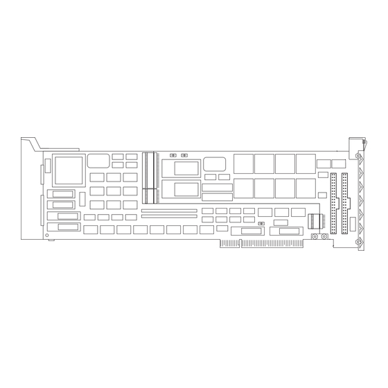
COM/Xi Boards The COM/Xi board is actually two boards, the COM/Xi Processor, and an I/O Mate that plug together to form a unit which occupies a single XT or AT slot (see Figure 1). The Processor board (or “motherboard”) is common to all versions of the COM/Xi, and contains a 10 MHz 80C188 microprocessor and 256K of dual-ported RAM. -
Page 15: Installation Tips
Installation Tips Installing your DigiBoard intelligent serial communications board is easy; however, since the boards require unique I/O and memory addresses, you may experience conflicts with other devices in your system. To minimize installation difficulties, two utilities have been provided: DIGIMMAP.EXE, a program which will help you find a block of available memory address space in your computer (needed for the board’s dual ported memory), and UD-CISC.EXE, a diagnostic program which will verify that the board is functioning correctly, and help you to... -
Page 16: Figure 1 Installation Flow Chart
Figure 1 Installation Flow Chart Run digimmap to map system. Choose I/O and memory addresses. Configure board (via DIP switches or POS). diagnostics. diagnostics pass? Install device driver. Installation Tips... -
Page 17: Memory Map Utility
Memory Map Utility The memory map utility, DIGIMMAP.EXE, is an MS-DOS based executable program that is designed to aid in the installation of DigiBoard hardware by detailing locations in memory that are available for the DigiBoard product. To run DIGIMMAP.EXE, follow this procedure: Boot your system normally. -
Page 18: User Diagnostics
User Diagnostics The \DIAGS directory on the DOS, AIO, OS/2 and Windows diskette contains a user diagnostic program called UD-CISC.EXE. Place the DOS, AIO, OS/2 and Windows diskette in the diskette drive and enter A:\DIAGS\UD-CISC (assuming that the diskette is in drive A). When asked for a board family, press the letter that corresponds to your board type (if you are installing a Micro Channel board, you will be asked for the number of the slot that the board is plugged into—the board type will... -
Page 19: Installing Pc/Xi Boards
Installing PC/Xi Boards Before you plug in the board... Write down the serial number of the processor board in the space provided. You will need it if you have to contact DigiBoard regarding the board. There are three jumpers and two banks of DIP switches which need to be set prior to installing the board in your computer. -
Page 20: Jumper Settings
Jumper Settings J1—Local Program Memory Size PC/Xi boards have a local RAM which is used for the on-board software. The default size of this memory is 16K, but it can be upgraded to 64K. Jumper J1 must be set to correspond to the size of the memory installed. J1 consists of three pins numbered 1, 2 and 3, and a jumper shunt which can connect either pins 1 and 2 or pins 2 and 3. -
Page 21: Dip Switch Settings
DIP Switch Settings PC/Xi boards have two banks of DIP switches labeled DS1 and DS2 (see Figure 2 for the location of the DIP switches). DS1 has eleven switches which are used to set the board’s I/O port address and the starting address of the board’s dual- ported memory. - Page 22 Please note that even though there are seven supported addresses below 1 megabyte, 0C0000h and 0D0000h are the only ones commonly available, and that a 128K board will take up the entire area from 0C0000h to 0DFFFFh. This can conflict with other peripherals such as ESDI and SCSI controllers, and EGA or VGA video adapters.
-
Page 23: Figure 3 Ds1, Sw1-8-Pc/Xi Memory Start Addresses (Below 1 Mb)
Figure 3 DS1, SW1-8—PC/Xi Memory Start Addresses (Below 1 MB) 9 10 11 9 10 11 080000h 090000h 9 10 11 9 10 11 0A0000h 0B0000h 9 10 11 9 10 11 0C0000h 0D0000h 9 10 11 0E0000h Notes— • 090000h, 0A0000h, 0B0000h, 0D0000h and 0E0000h can only be used by PC/Xi boards configured for 64K of dual-ported memory. -
Page 24: Figure 4 Ds1, Sw1-8-Pc/Xi Memory Start Addresses (Above 1 Mb)
Figure 4 DS1, SW1-8—PC/Xi Memory Start Addresses (Above 1 MB) 9 10 11 9 10 11 D00000h D80000h 9 10 11 9 10 11 E00000h E80000h 9 10 11 9 10 11 F00000h F80000h 9 10 11 9 10 11 FA0000h FC0000h Notes—... -
Page 25: I/O Port Address-Ds1, Switches 9-11
I/O Port Address—DS1, Switches 9-11 Each PC/Xi board must have a unique I/O port address. This address must not be used by any other device in the system, including other PC/Xi boards. The I/O port address is determined by setting switches 9, 10 and 11 of DIP switch DS1 as shown below. -
Page 26: Interrupt Request (Irq) Line-Ds2
Interrupt Request (IRQ) Line—DS2 DS2 is used to specify which IRQ line will be used by the board to interrupt the host. Each board must have its own unique IRQ selection, and that IRQ line must not be used by any other device in the system. Select the IRQ by setting the appropriate switch in DS2 as shown below. -
Page 27: Board Installation-Pc/8I
Board Installation—PC/8i Plug the board into a full-length AT (16-bit) slot and screw the endplate to the computer chassis. Install the interface cable assembly or connector box (see Connector Options on page 45) on the PC/Xi board by mating the female 78-pin connector on the assembly to the male 78-pin plug on the end of the PC/Xi board. -
Page 28: Board Installation-Pc/16I
Board Installation—PC/16i Place the connector box assembly near the open slot at the rear of the machine. Thread the two gray ribbon cables through the slot so that the two plugs are pointing toward the bus connector into which you intend to plug the board. -
Page 29: Installing Pc/16E Boards
Installing PC/16e Boards Before you plug in the board... Write down the serial number of the board in the space provided. You will need it if you have to contact DigiBoard regarding the board. There are two banks of DIP switches and one jumper which need to be set prior to installing the board in your computer. -
Page 30: Jumper Settings
Jumper Settings J1—Local Program Memory Size PC/16e boards have a local RAM which is used for the on-board software. The default size of this memory is 16K, but it can be upgraded to 64K. Jumper J1 must be set to correspond to the size of the memory installed. J1 consists of three pins numbered 1, 2 and 3, and a jumper shunt which can connect either pins 1 and 2 or pins 2 and 3. -
Page 31: Installing Mc/Xi Boards
Installing MC/Xi Boards Before you plug in the board... Write down the serial number of the processor board in the space provided. You will need it if you have to contact DigiBoard regarding the board. Also, be sure to have on hand the DigiBoard ADF (Adapter Description Files) diskette, and a working copy of your IBM Reference Diskette (don’t use the original—it should be write protected and stored in a safe place). -
Page 32: Jumper Settings
Jumper Settings J1—Dual Ported Memory Window Size There is only one jumper on the MC/Xi board that needs to be set by the user. This is J1, located above the edge connector on the processor board (see Figure 9 on page 20). Jumper J1 determines whether the MC/Xi board’s dual-ported memory window size will be 32K or 128K. -
Page 33: Other Jumpers
Other Jumpers The MC/Xi I/O Mates have two jumpers, located near the EPROMs, which identify the size of the EPROMs on the board. These jumpers are set at the factory, and should only be changed if you are installing custom EPROMs. On RS-232 versions of the MC/Xi, the jumpers are labeled J5 and J6. -
Page 34: Board Installation - Mc/4I And Mc/8I
Board Installation - MC/4i and MC/8i Plug the MC/4i or MC/8i board into the Micro Channel slot, making sure that the “fork” is in position under the endplate thumbscrew. Tighten the thumbscrew. Install the interface cable assembly or connector box (see Connector Options on page 45) on the MC/Xi board by mating the female 78-pin connector on the assembly to the male 78-pin plug on the end of the MC/Xi board. -
Page 35: Board Installation - Mc/16I
Board Installation - MC/16i Place the connector box assembly near the open slot at the rear of the machine. Thread the two gray ribbon cables through the slot so that the two plugs are pointing toward the bus connector into which you intend to plug the board. -
Page 36: Configuring The Mc/Xi Board
Configuring the MC/Xi Board After the MC/Xi board has been physically installed in your machine, you need to configure the board for operation in your system. This is done by running the configuration program on the IBM Reference Diskette. Insert your working copy of the IBM Reference Diskette into your boot drive (Drive A) and turn on the computer’s power. - Page 37 ADF Files Different Adapter Description Files are necessary for the MC/Xi, depending upon the individual configuration of the board (number of ports, memory size and interface type). These files are supplied on a diskette shipped with the MC/Xi board. The ADF diskette contains the following files: 4 &...
-
Page 38: Installing Com/Xi Boards
Installing COM/Xi Boards Before you plug in the board... Write down the serial number of the processor board in the space provided. You will need it if you have to contact DigiBoard regarding the board. Several jumpers need to be set to configure the board’s I/O address, dual ported memory start address and IRQ line. -
Page 39: Jumper Settings
Jumper Settings The COM/Xi Processor board has three sets of jumpers which determine the I/O port address, the interrupt request (IRQ) line and the starting address of the board’s dual-ported memory window. See your software installation instructions for recommended address and IRQ selections. Memory Start Address—Jumpers J15, J16 and J17 The COM/Xi board has 256K of on-board RAM which is accessible to the host computer through a 32K “window”... -
Page 40: I/O Port Address-Jumpers J2, J3 And J4
I/O Port Address—Jumpers J2, J3 and J4 Each COM/Xi board must have a unique I/O port address. This address must not be used by any other device in the system, including other COM/Xi boards. The I/O port address is determined by setting jumpers J2, J3 and J4 as shown below. Figure 15 J2-J4—COM/Xi I/O Port Addresses 100h... -
Page 41: Interrupt Request (Irq) Line-J5-J14
Interrupt Request (IRQ) Line—J5-J14 Jumpers J5-J14 are used to specify which IRQ line will be used by the board to interrupt the host. Each board must have its own unique IRQ selection, and that IRQ line must not be used by any other device in the system. - Page 42 IRQs 10-15 can only be used if the board is plugged into an AT (16 bit) slot. Installing COM/Xi Boards...
-
Page 43: Eprom Size Jumpers-J1 And J2
EPROM Size Jumpers—J1 and J2 The I/O Mate (daughter card) has two jumpers, J1 and J2, which indicate the size of the EPROM (see Figure 13 on page 27 for the location of J1 and J2). These jumpers are set at the factory, and should only be changed by the user when a customized EPROM is installed. -
Page 44: Board Installation-Com/Xi
Board Installation — COM/Xi The COM/Xi board is an 8-bit board, but is equipped with an AT-style dual edge connector to facilitate the use of IRQs 10, 11, 12 and 15. When using IRQs 2-7, or no IRQ, the board may be installed in an XT (8-bit) slot, provided that there is clearance at the end of the slot for the extra edge connector. -
Page 45: Connecting Peripherals
Connecting Peripherals Connecting to a Modem DB-9 Equipped Boards To connect a DB-9 equipped board to a modem, use standard PC modem cables, available from most electronics stores and computer dealers. The wiring dia- gram for a 9-pin to 25-pin modem cable is shown in Figure 17. Figure 17 DB-9 to DB-25 Modem Cable DB-9 Female... -
Page 46: Figure 18 Db-25 To Db-25 Modem Cable
DB-25 Equipped Boards Figure 18 DB-25 to DB-25 Modem Cable DB-25 Female DB-25 Male Signal Signal Shell Cable Shield) To connect a DB-25 equipped board to a modem, use a standard “straight- through” cable (see Figure 18) to connect the modem to one of the DB-25 con- nectors on the fan out cable or connector box. -
Page 47: Rj-45 Equipped Boards
RJ-45 Equipped Boards The simplest way to connect a modem to a board with RJ-45 connectors is to use RJ-45 to DB-25 “Cable Legs”, available from DigiBoard (see page 53 for a description and part numbers). These adapters use 10-pin RJ-45 plugs, and therefore provide full modem support (Ring Indicator and Data Carrier Detect are only available on 10-pin RJ-45 connectors). -
Page 48: Altpin Modem Wiring (Rj-45 Versions)
ALTPIN Modem Wiring (RJ-45 Versions) 10-pin RJ-45 plugs may be difficult to obtain in the retail market; therefore, most DigiBoard device driver software incorporates an optional feature called ALT- PIN, which swaps the logical functions of DSR (Data Set Ready) with DCD (Data Carrier Detect). -
Page 49: Connecting To A Dte Device
Connecting to a DTE Device A DTE device is a terminal, serial printer, another computer’s serial port, etc. To connect the PC/Xi, MC/Xi or COM/Xi board (which are also DTE devices) to another DTE device, you need a null modem cable or adapter. DB-9 Equipped Boards Use a standard PC printer cable, or build a cable as shown in Figures 21 or 22. -
Page 50: Figure 22 9-Pin Null Modem Cable
Figure 22 9-Pin Null Modem Cable Signal Signal Shell Shell Cable Shield) Connecting Peripherals... -
Page 51: Db-25 Equipped Boards
DB-25 Equipped Boards Software Handshaking (XON/XOFF) In most cases, serial terminals and printers need only a “three-wire” connection to the board. All DigiBoard device driver software supports XON/XOFF (software) handshaking, so the only signal lines necessary are Transmitted Data (TxD), Received Data (RxD) and Signal Ground (SG). It may be necessary to disable DCD (Data Carrier Detect) sensing through a software command—see your DigiBoard device driver software manual for instructions. -
Page 52: Hardware Handshaking (Ready/Busy)
Hardware Handshaking (Ready/Busy) Figure 24 Terminal/Printer Cable with DTR Handshaking (DB-25) DB-25 Female DB-25 Male Signal Signal Shell Cable Shield) Most terminals and printers use Data Terminal Ready (DTR) for Ready/Busy hardware handshaking. The cable shown in Figure 24 supports this method. Some Okidata printers use a control signal on pin 11, called Supervisory Send Data (SSD) instead of DTR. -
Page 53: Rj-45 Equipped Boards
RJ-45 Equipped Boards Software Handshaking (XON/XOFF) In most cases, serial terminals and printers need only a “three-wire” connection to the board. All DigiBoard device driver software supports XON/XOFF (software) handshaking, so the only signal lines necessary are Transmitted Data (TxD), Received Data (RxD) and Signal Ground (SG). It may be necessary to disable DCD (Data Carrier Detect) sensing through a software command—see your DigiBoard device driver software manual for instructions. -
Page 54: Hardware Handshaking (Ready/Busy)
Hardware Handshaking (Ready/Busy) Figure 26 Terminal/Printer Cable with DTR Handshaking (RJ-45) RJ-45 - 8 Pin DB-25 Male Signal Signal Cable Shield) Some Okidata printers use a control signal on pin 11, called Supervisory Send Data (SSD) instead of DTR. In this case, simply connect CTS on the RJ-45 side to pin 11 of the DB- 25, instead of pin 20. -
Page 55: Rs-232 Cables And Connector Options
RS-232 Cables and Connector Options Cables RS-232 serial interface cables should be shielded, low capacitance cables, ide- ally designed specifically for serial data transmission. Grounding The shield should be grounded at both ends of the cable. Chassis Ground— available on the shell of DigiBoard’s DB-25 and DB-9 connectors, and pin 4 of our 10-pin RJ-45 connector, is ideal for this purpose. -
Page 56: Connector Options
Connector Options A variety of connector types is available. Four and eight-port boards can be set up with DB-25 connectors (male or female, DTE or DCE wiring), DB-9 connectors (male or female, DTE wiring) or 10-pin RJ-45 jacks. Sixteen-port boards are available only with DB-25 connectors (male, DTE wiring). The following pages give the part numbers and wiring information for the various connector types. -
Page 57: Quad And Octa Cable Option (Dte Or Dce)
DB-25 Connector Options (Four and Eight-Port Boards) DB-25 connectors are available in two styles: a quad or octa cable assembly, or a connector box assembly. Either style may be ordered with male or female DB- 25 connectors, configured as DTE or DCE devices. Quad and Octa Cable Option (DTE or DCE) Figure 27 Octa-Cable Assembly... -
Page 58: Quad And Octa Connector Boxes (Dte Or Dce)
Quad and Octa Connector Boxes (DTE or DCE) Figure 28 Eight-Port DB-25 Connector Box Figure 28 shows the eight-port DB-25 connector box option. A four-port box is also available. Table 7 Connector Box Options and Part Numbers DB-25 Male DB-25 Female DTE Quad 7600030 7600026... -
Page 59: Connector Options (Pc/16I And Mc/16I Boards)
DB-25 Connector Options (PC/16i and MC/16i Boards) PC/16i and MC/16i boards are available with male DB-25 connectors, configured for DTE operation. The connector box (shown below) is attached to the board via two ribbon cables which mate to connectors P2 and P3 on the PC/16i board, or P5 and P6 on the MC/16i board. -
Page 60: Db-9 Connectors
DB-9 Connectors Four and eight-port boards can be configured with male or female DB-9 connec- tors (DTE wiring only). DB-9 connectors are available only in the “fan-out” cable configuration (see Figure 27, on page 46). Table 8 DB-9 Quad and Octa Cable Options and Part Numbers DB-9 Male DB-9 Female DTE Quad... -
Page 61: Figure 30 Eight-Port Rj-45 Connector Box
RJ-45 Connectors Figure 30 Eight-Port RJ-45 Connector Box Table 10 RJ-45 Connector Box Options and Part Numbers Quad Octa RJ-45 76000038 76000033 Four and eight-port boards can be configured with 10-pin RJ-45 modular jacks. These accept plastic snap-in plugs like the ones used for connecting telephones. They are less bulky and more convenient to use than the DB-25, but have not undergone the standardization rigors that have been applied to the larger DB-25 connectors. -
Page 62: Figure 31 Rj-45 Connector Box For Pc/16E Boards
Figure 31 RJ-45 Connector Box for PC/16e Boards 1 1 0 0 1 1 2 2 1 1 3 3 1 1 4 4 1 1 5 5 1 1 6 6 RS-232 Cables and Connector Options... -
Page 63: Modular Plugs
Modular Plugs There are four types of modular plugs that can be used with DigiBoard’s RJ-45 10-pin jack. These are the 4 or 6-pin RJ-11 plugs, and the 8 or 10-pin RJ-45 plugs. The 8 and 10-pin RJ-45 plugs are the same physical size, but the 10-pin version has one additional wire at each end of the row of contacts. -
Page 64: Rj-45 To Db-25 Conversion
RJ-45 to DB-25 Conversion Figure 32 RJ-45 to DB-25 “Cable Leg” RJ-45 - 10 Pin DB-25 Signal Signal Shell Chassis Ground Chassis Ground Signal Ground Signal Ground Table 11 Cable Leg Options and Part Numbers DB-25 Male DB-25 Female DB-9 Male 24 Inch Cables 6102024 6103024... -
Page 65: Cables
RS-422 Asynchronous Serial Interface MC/Xi, COM/Xi and PC/16i boards are available in an optional RS-422 configuration which provides asynchronous serial data communication over differential lines. This permits cable lengths much longer than those supported by an RS-232 interface (up to 4000 feet), and has better noise immunity at high baud rates. -
Page 66: Connectors
Connectors The following table shows the pin configurations for the RS-422 versions of the DB-9 and DB-25 connectors. Table 12 DB-9 and DB-25 Connector Wiring for RS-422 Boards DB-9 Pin DB-25 Pin Signal Description (4i & 8i Boards) (16i Boards) TxD+ Transmitted Data (+) TxD-... -
Page 67: Interconnecting Devices
Interconnecting Devices The RS-422 interface provides four signals: Transmitted Data (TxD), Received Data (RxD), Request To Send (RTS) and Clear To Send (CTS). The functions of these signals is identical to their RS-232 counterparts. Note that two wires are required for each signal, a positive lead (“+”), and a negative lead (“-”). -
Page 68: Figure 34 Rs-422 Null Modem For Software Handshaking
Figure 34 RS-422 Null Modem for Software Handshaking DigiBoard (DTE) DigiBoard (DTE) Peripheral (DTE) Peripheral (DTE) Figure 35 RS-422 DTE to DCE Connection DigiBoard (DTE) DigiBoard (DTE) Modem (DCE) Modem (DCE) RS-422 Asynchronous Serial Interface... -
Page 69: Synchronous Serial Interface-Mc/Xi
Synchronous Serial Interface—MC/Xi A special version of the MC/Xi board, called the MC/Xi+ is available in four and eight-port configurations. The MC/Xi+ board has a synchronous port in addition to the standard asynchronous ports. RS-232 The MC/Xi+ synchronous port uses a 10-pin RJ-45 jack located above the DB- 78 connector on the endplate. -
Page 70: Table 13 Mc/Xi+ (Rs-232) Synchronous Port Pin Assignments
The table below shows the pin assignments for the RJ-45 jack. Dual function pins also show the jumper settings required for each function. Signals ending with “A” connect to the “A” port of the 8530 communications controller, and signals ending with “B” connect to the “B” port of the 8530. Table 13 MC/Xi+ (RS-232) Synchronous Port Pin Assignments RJ-45 Pin... -
Page 71: Figure 37 Mc/8I+ (Rs-422) Synchronous Port And Jumpers
RS-422, RS-422/RS-485 The MC/Xi+ board is also available in RS-422 and RS-422/RS-485 configurations. As with the RS-232 versions, there is an extra port wired for synchronous communication. The RS-422 version, the synchronous port is set up for RS-422 operation. The RS-422/RS-485 version has four or eight RS-422 asynchronous ports plus one RS-485 synchronous port. -
Page 72: Table 14 Mc/Xi+ (Rs-422) Synchronous Port Pin Assignments
The table below shows the pin assignments for the RJ-45 jack. Dual function pins also show the jumper settings required for each function. Table 14 MC/Xi+ (RS-422) Synchronous Port Pin Assignments RJ-45 Pin Signal Name Jumpers CTS+ Clear To Send (+) J1 Pins 1 &... -
Page 73: Synchronous Serial Interface-Pc/Xi
Synchronous Serial Interface—PC/Xi A special version of the PC/Xi board, called the PC/Xi+ is available in eight and sixteen-port configurations. The PC/Xi+ board has an RS-232 synchronous port in addition to the standard asynchronous ports. PC/8i+ The PC/8i+ synchronous port uses a 10-pin RJ-45 jack located above the DB-78 connector on the endplate. -
Page 74: Table 15 Pc/8I+ Synchronous Port Pin Assignments (Rj-45)
The table below shows the pin assignments for the PC/8i+ RJ-45 jack. Dual function pins also show the jumper settings required for each function. Signals ending with “A” connect to the “A” port of the 8530 communications controller, and signals ending with “B” connect to the “B” port of the 8530. Table 15 PC/8i+ Synchronous Port Pin Assignments (RJ-45) RJ-45 Pin... -
Page 75: Table 16 Pc/16I+ Synchronous Port Pin Assignments (Db-25)
PC/16i+ The PC/16i+ has an additional DB-25 connector on the back of the connector box assembly. The following table shows the pin assignments for this connector. Table 16 PC/16i+ Synchronous Port Pin Assignments (DB-25) DB-25 Pin # Signal Description Shell Chassis Ground Transmitted Data Received Data... -
Page 76: Specifications
Specifications Power Requirements PC/16i (RS-232) +5 VDC 1.7 Amps max. +12 VDC 200 mA max. -12 VDC 200 mA max. PC/16i (RS-422) +5 VDC 1.85 Amps, plus 60 mA per channel under load. PC/16e +5 VDC 2.0 Amps max. +12 VDC 130 mA max. - Page 77 COM/8i (RS-422/RS-485) +5 VDC 1.2 Amps, plus 60 mA per channel under load. COM/8i (RS-422/RS-485) +5 VDC 1.1 Amps, plus 60 mA per channel under load. MC/16i (RS-232) +5 VDC 1.6 Amps max. +12 VDC 300 mA max. -12 VDC 300 mA max.
-
Page 78: Board Dimensions
Board Dimensions PC/Xi, PC/16e Length 13.1 inches Width 0.6 inches Height 4.8 inches Weight 1.0 pound MC/Xi Length 11.5 inches Width 0.6 inches Height 3.5 inches Weight 0.75 pounds COM/Xi Length 11.5 inches Width 0.6 inches Height 4.2 inches Weight 1.25 pounds Environmental All Boards... -
Page 79: Appendix-Memory Conflicts
Appendix — Memory Conflicts Contention for Memory Addresses Many intelligent peripheral devices require a block of vacant memory addresses on the host computer’s bus for their own use. These memory addresses may be used to access a dual-ported RAM on the peripheral device to facilitate the transfer of large volumes of data between the host and the peripheral (memory- to-memory transfers are much faster than I/O bus transfers), or they may point to a ROM BIOS (a firmware program used by the host computer to control the... -
Page 80: Figure 39 Typical Pc Memory Usage - 1St Megabyte
Figure 39 Typical PC Memory Usage - 1st Megabyte 1024K FFFFFh (1 Meg) System BIOS F0000h EFFFFh BIOS Extensions (EBIOS) EMM, LIM 4.0 E0000h DFFFFh SCSI Interface D8000h Ethernet D7FFFh LAN Adapters D0000h 128K ESDI Hard Disk Drive CFFFFh SCSI Interface C8000h C7FFFh EGA/VGA ROM BIOS... -
Page 81: Pc/Xi And Pc/16E Issues
PC/Xi and PC/16e Issues PC/Xi boards can be ordered with 128K, 256K or 512K of RAM. PC/Xi boards with 128K of RAM can be configured for 64K operation by changing a jumper setting on the board see page. PC/16e boards are only available with 64K of RAM. -
Page 82: Conflicts Between 8-Bit And 16-Bit Memory Devices
Conflicts Between 8-Bit and 16-Bit Memory Devices The ISA (Industry-Standard Architecture) bus, used in many 80286 (AT compatible), 80386, 80486 and Pentium based computers, supports 16-bit memory and peripherals with 16-bit dual-ported memory or ROM. By default, however, memory devices are considered to be 8-bit devices. 16-bit devices must declare themselves by raising a flag, so that the host knows whether it is referencing a byte (8 bits) or a word (16 bits) of memory. -
Page 83: Mc/Xi Issues
MC/Xi Issues MC/Xi boards can be configured for either 128K or 32K of dual-ported memory by the placement of a jumper, J1, located on the MC/Xi Processor board, just above the edge connector (see Figure 9 on page 20). The 128K MC/Xi board’s dual-ported memory can be addressed at C0000h (below 1 megabyte), or at one of several addresses in the 16th megabyte. -
Page 84: Com/Xi Issues
COM/Xi Issues The COM/Xi board has 256K of on-board RAM which can be accessed by the host computer through a 32K window on the host’s memory bus. COM/Xi’s 32K window can be mapped into one of four address ranges on the host memory bus: C0000h-C7FFFh, C8000h-CFFFFh, D0000h-D7FFFh or D8000h-DFFFFh. -
Page 85: Conflicts Between 8-Bit And 16-Bit Memory Devices
Conflicts Between 8-Bit and 16-Bit Memory Devices The ISA (Industry-Standard Architecture) bus, used in many 80286 (AT compatible), 80386, 80486 and Pentium based computers, supports 16-bit memory and peripherals with 16-bit dual-ported memory or ROM. By default, however, memory devices are considered to be 8-bit devices. 16-bit devices must declare themselves by raising a flag, so that the host knows whether it is referencing a byte (8 bits) or a word (16 bits) of memory. -
Page 86: Index
Index 4 pin, 51 Adapter Description Files, 25, 26 ADF files, 25, 26 6 pin, 51 ALTPIN, 36 RJ-45 10 pin, 51 Cable configuration RS-232 peripherals, 35, 39, 40, 8 pin, 51 RS-422, 54 41, 42 Cable legs, 35 Contention RJ-45 to DB-25, iv, 52 Memory addresses, 67 Sources, 71... - Page 87 DB-25, 44 COM/Xi, 30 DB-9, 48 MC/Xi, 25 MC/Xi+ Synchronous port (RS- PC/Xi, PC/16e, 15 Jumpers 422/RS-485), 60 MC/Xi+ PC/Xi+ Synchronous port (DB- Synchronous port (RS- 232), 57 25), 63 Synchronous port (RJ-45), MC/Xi+ (RS-232), 57 MC/Xi+ (RS-422/RS-485), 59 Synchronous port RS-422, 54 Synchronous port (RS-232), 58 PC/8i+, 61...
- Page 88 Artisan Technology Group is your source for quality new and certified-used/pre-owned equipment SERVICE CENTER REPAIRS WE BUY USED EQUIPMENT • FAST SHIPPING AND DELIVERY Experienced engineers and technicians on staff Sell your excess, underutilized, and idle used equipment at our full-service, in-house repair center We also offer credit for buy-backs and trade-ins •...
Need help?
Do you have a question about the DigiBoard PC/ i Series and is the answer not in the manual?
Questions and answers