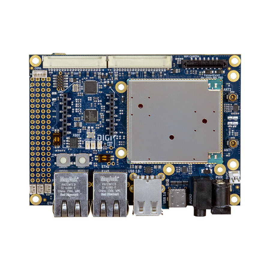
Digi ConnectCore 8X Hardware Design Manuallines And Checklist
Hide thumbs
Also See for ConnectCore 8X:
- Hardware reference manual (116 pages) ,
- Hardware reference manual (21 pages) ,
- Hardware reference manual (89 pages)
Table of Contents
Advertisement
Quick Links
Advertisement
Table of Contents

Summary of Contents for Digi ConnectCore 8X
- Page 1 ConnectCore 8X Hardware Design Guidelines and Checklist...
- Page 2 Information in this document is subject to change without notice and does not represent a commitment on the part of Digi International. Digi provides this document “as is,” without warranty of any kind, expressed or implied, including, but not limited to, the implied warranties of fitness or merchantability for a particular purpose.
- Page 3 Feedback To provide feedback on this document, email your comments to techcomm@digi.com Include the document title and part number (ConnectCore 8X Hardware Design Guidelines, 90002394 A) in the subject line of your email. ConnectCore 8X Hardware Design Guidelines...
-
Page 4: Table Of Contents
Contents About this document Overview Naming and signal conventions Design checklist Power supply Boot Console debug port Wireless and Bluetooth CPU control lines PCIe ADCs Schematics Bring-up guidelines Power-up Power rails Verify system boot ConnectCore 8X Hardware Design Guidelines... -
Page 5: About This Document
This document, together with the ConnectCore 8X System-on-Module Hardware Reference Manual, provide information key to ensuring a functional, quality design featuring the ConnectCore 8X module. Naming and signal conventions This document is written assuming the reader has a good working knowledge of common electronics terminology. -
Page 6: Design Checklist
This excessive heating can permanently damage the microprocessor and/or its supporting components. Power supply ☑ Item Description 1. Minimum 1 x 100 uF + 1 x 10 uF + 1 x 1 uF decoupling capacitors VSYS/VSYS2 ConnectCore 8X Hardware Design Guidelines... - Page 7 RTC mode operation which could cause undesirable RTC behavior. Digi has validated that using a comparator instead of a direct connection drastically improves the transitory time that the system takes to go from normal operation to RTC mode. See Comparator used for connecting MCA_VIN_DET line used on the ConnectCore 8M Nano DVK.
-
Page 8: Boot
Serial downloader Boot from board settings Reserved Digi recommends you configure the boot mode lines to boot by default from the internal eMMC of the module. This means: BOOT_MODE0 pulled-down through 100 K resistor BOOT_MODE1 pulled-high through 4.7 K resistor... -
Page 9: Mca
4. MCA Digi recommends you enable access to the SWD port of the MCA in the carrier recovery board. This will allow you to recover the MCA in case its firmware gets corrupted and the micro-controller can no longer boot. -
Page 10: Cpu Control Lines
SCU_PMIC_STANDBY is the standby signal of the PMIC, and it is also controlled PMIC_ internally in the SOM. It can be used externally for managing external circuitry, but STANDBY must never be driven as an input. ConnectCore 8X Hardware Design Guidelines... -
Page 11: Pcie
Decoupling capacitors in the transmission data lines must be set externally. ADCs ☑ Item Description Digi recommends you use VDD_ADC_1V8 as the CPU ADCs voltage reference, this ADC_ means, connecting VDD_ADC_1V8 (pad AG24) to ADC_VREFH (pad J29). VREFH ConnectCore 8X Hardware Design Guidelines... -
Page 12: Schematics
Schematics Coin-cell/supercap connected to VCC_MCA through Schottky diode Comparator used for connecting MCA_VIN_DET line ConnectCore 8X Hardware Design Guidelines... - Page 13 Schematics Boot mode switches for selecting the boot source of the module ConnectCore 8X Hardware Design Guidelines...
-
Page 14: Bring-Up Guidelines
Bring-up guidelines This section offers guidelines for performing bring-up of a ConnectCore 8X-based product. Power-up The very first power-up of a product is one of the most critical step of the bring-up. Use a power supply with current limiter so the system is protected in case an unexpected short (or any other high- current incident) occurs. -
Page 15: Verify System Boot
Verify the value of the BOOT_MODE lines. Verify that MCA_VIN_DET is at high level (3.3 V). Verify that POR_B signal is at high level. Note For more information, see the ConnectCore 8X System-on-Module Hardware Reference Manual. ConnectCore 8X Hardware Design Guidelines...


Need help?
Do you have a question about the ConnectCore 8X and is the answer not in the manual?
Questions and answers