Table of Contents
Advertisement
Quick Links
Advertisement
Table of Contents

Related Manuals for Digi SYNC/570i


Summary of Contents for Digi SYNC/570i
- Page 1 USER’S MANUAL SYNC/570i S Y N C / 5 7 0 Synchronous Expansion Boards 90500018C...
- Page 2 Digi International Inc. The D&i Digi International is a a trademadr of Digi International Inc. Au other brand and product names are logo is the trademarks of their respective holders. 63 Digi International Inc. 1996 AR Rights Reserved...
- Page 3 FCC Information for the ISA SYNC/5701 The ISA SYNC/57Oi has been tested and found to comply with the limits for a Qass B computing device pursuant to Subpart J of Part 15 of FCC rules. Warning: Changes or modifications to this unit not expressly approved by the party responsible for comphance could void the user’s authority to operate the equipment.
-
Page 4: Table Of Contents
TABLE OF CONTENTS Introduction ..........l Protecting Your Equipment and Data. - Page 5 LIST OF FIGURES SYNC/570 DB-15 female connector and connector pin assignments ..............Cable DE25 male connector and connector pin assignments..4 2 SYNC/570 DB-15 male loopback connector wiring diagram..
-
Page 7: Introduction
CHAPTER ONE Introduction The Digi SYNC/570 and the SYNCY57Oi are high-performance expansion boards for ISA or Micro Channel computers. The SYNC/570 adds two syn- chronous/asynchronous serial ports while the SYNW57Oi adds two or four synchronous/ asynchronous ports. They are designed for applications requiring cost-effective communications. - Page 8 HI64570 chip supports two synchronous/asynchronous ports and four channels of DMA as well as interrupt and timer logic. Digi SYNC/57Oi is available with several interface options. Interface specific information (interface setting instructions, cables, connector information) can be found in the interface appendices.
-
Page 9: Protecting Your Equipment And Data
To protect against lightning, electrical surges, and power fluctuations, Digi recommends uninterruptible power supplies CUPS), power line filters, and surge protectors for every installation. - Page 10 Using a receptacle for only the computer and terminal also protects against data errors or equipment damage. Sharing the receptacle with noise- producing devices such as fax machines, printers, calculators, and heaters may allow noise pickup. Grounding T e c h n i q u e s Many terminals and computers are dependent on earth ground to set a reference for signal ground.
- Page 11 Make sure that you are working in a static-controlled area which includes at least a conductive benchtop mat or chair mat that is electrically connected to earth ground. Conductive wrist straps in conjunction with ground cords provide extra protection for handling electronic components. Always store and/or move individual printed circuit boards in a conductive bag.
- Page 12 Chapter Two: Protecting Your Equipment and Data...
-
Page 13: Checking Your Package Contents
CHAPTER THREE Checking Your Package Contents After opening the shipping box, check the contents. WARNING Lease the board in ttspmttxti~ anti-static bag until tnstalkatton. When tnstalling or movtng boa&, always use adequutepmautions Gucb as a groundtng strap) topmmt electrostatic damage. sMyc/570 Contents: SYNC/570 board Two, g-foot, DB-15 to DE25 cables... - Page 14 Chapter Three: Checking Your Package Contents...
- Page 15 CHAPTER FOUR Installing the SYNC/570 SYNC/57Oi &!L WARNING power cord. Insetttng ‘15cm ofl$ower to your cornwet- and disconnect a board into the system u&power applied could damage the system, the board, or both. Such abuse wtll void yrmr warranty. Remove the cover of the computer (see computer mantiacturer’s instructions~.
- Page 16 Secure the board by tightening the thumb screw or replacing the board hold-down screw that was removed in Step 2. Replace the computer cover and reconnect the power cord Complete the software configuration of the board. Chapter Four: Installing the SYNC/570 and SYNC/570i...
-
Page 17: Setting The Isa Sync/570 And Sync/57Oi Switch
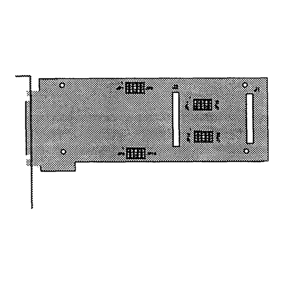
CHAPTER FIVE Setting the ISA SYNC/570 and SYNC/57Oi Switch Before installing the SYNC/570 or SYNC/57Oi in an ISA system, set the multi-segment switch on the board The setting of the switch selects the starting address of the block of I/O locations which the SYNC/570 or SYNC/57Oi uses. - Page 18 Address switchsewgs Chapkr Five: Setting the ISA SYNC/570 and SYNC/570i Switch...
- Page 19 jPaeerR6l I 2 3 4 4 b 25oH 27OH...
- Page 20 Chapter Five: Setting he ISA SYNC/570 and SYNC/570i Switch...
-
Page 21: Configuring The Micro Channel Sync/570 And Sync/57Oi
Configure the SYNC/570 and SYNW57Oi through your computers Micro Channel Programmable Options Select @OS) system, using data from the Digi Adapter Definition File (ADI on the diagnostic diskette. This system uses hardware registers, selected and loaded through software, to assign system resources to an expansion board. - Page 22 (The instructions vary for computers ma& by different manufacturers.) When you are prompted to copy the new adapter files, insert the Digi Diagnostics Diskette. Press ENTER. The computer will read the @6163.ADP file.
-
Page 23: Connectingperipherals
SYNC/570 or SYNC/57Oi. If you supply your own cables for SYNC/570 or SYNC/57Oi, Digi recommends shielded cables (15 pF or less capacitance per foot) for all installations. The FCC requires the use of shielded cables to comply with EMI/RFI emission limits. - Page 24 Chapter seven: Connecting Periphemls...
-
Page 25: Using The Diagnostics Disk
I/O address. You may modify the address and IRQ selections from the diagnostics. The IRQ must be active, and you must select a non-zero address. If you cannot determine a setting, call Digi Customer Support for assistance. - Page 26 When IRQ and address selection are acceptable, the adapter memory is tested. ‘Ihe test does write/verify at every location with word accesses only. Each 16K memory window is selected and tested independently. Address and data buses are tested separately. The program then runs a window uniqueness test. A different, single word is written to each of the eight 16K windows;...
-
Page 27: Incaseoftrouble
CHAPTER NINE In Case of Trouble WARNING Make sum your computer 13 turned off befom hstalltng or nvrwuing boar& When installhzg or removing boards, always use adequutepre- cautions b4ch as a grvunding strap) top- electnxtattc damage. Test your SYNC/570 or SYNC/57Oi using the diagnostics disk provided If the SYNC/570 or SYNW7Oi passes all the tests, the problem is probably elsewhere. - Page 28 If your board fails the diagnostics or you are unable to isolate the problem, call Digi Technical Support @OO-344-4273) anytime between 8 a.m. and 6 p.m. Central Time (Monday through Friday). We can give you suggestions for things to try. Please have the following information ready when you...
- Page 29 In this case, you’ll need to call us for an RMA number. You must have an RMA number to return a board to Digi. The RMA number must appear on the outside of the package. Before calling for the number, make sure...
- Page 30 Chapter Nine: in Case of Trouble...
-
Page 31: Sync/570 Host Adapter Eia-232-D Interface
APPENDIX A SYNC/570 Host Adapter EIA 2321) Interface The SYNC/570 has two high density 15pin D-subminiature female port connectors. The connectors provide an EIA 232D interface and serial data transmission and reception. Your application may specify the cable configuration required for connecting modems to a computer. - Page 32 pin assignmenI5 Figure 2, Cab& 08-25 male conneckr and cannector Notcumecbd Tmnsmitbd Data (TXO) -m(RxD) 5igmlGmund Cmior (DCD) Data Debct ReceimClock(RXCl Cbck Tmnunit (TXC) Cbck (TXC4 Tmnsmit Data Tuminal Ready (DTltj shell CGND When prompted by the diagnostics, insert the male loopback connector into the female DE15 connector on the SYIW570.
-
Page 33: V.35/Eia-232-D Daughterboard (Sync/57Oi)
APPENDIX B V.35/EIA-232-D Daughterboard (SYNC/57Oi) Fiium 5,5YNc/57oi 4-Port, v.35 daughkriloald Jumper Setdng for Interface Selecdon Before installing the SYNW57Oi in your system, make sure the jumper block on the board is set for the correct interface - or V.35. EZA-232-D WARNING When disconnecting the &ughte&oard in order to set the jumper, use... -
Page 34: Appendixc
Set the jumpers for the correct interface as described below. Remove the screws securing the daughterboard to the SYNC/57Oi. Pull the daughterboard from the SYNU57Oi. mere are two connectors holding the daughterboard. Do not use a twisting motion.) Install the jumper for the correct interface for each port. The positions of the jumpers are shown in Figures 4 and 5. - Page 35 CoMectors and c*ling The cable included in the SYNW7Oi V.35 package has a DB-37 (two port cable) or a DB-62 (four port cable) male connector on the board end, and DE25 male connectors on the peripheral end. The connectors provide a V.35 or an E&232-D interface and serial data transmission and reception.
- Page 36 Fgun 9, C mmier cab40 V.35 male camector p’bout and pin as+mmts CGND @-.C Z-O-. o--H TXDIsl RxD(BI TXCtJCOUT[cy RXCwAl TXClKOUT(Bj RXCU@I When prompted by the diagnosics, insert the female loopback connector into the male DB-25 connector on the SYNW7Oi cable. bopback connector wing diimms Figurn 10, V.35 and EIA-232-D DE25 female v.35...
- Page 37 APPENDIX C X.2 1 /EIA-530 (EIA-422) Daughterboard (SYNC/57Oi) x.21 coMecmrsandcabuflg cable included in the SYNW57Oi X.21 package has a DB-44 male connector on the board end, and two DB-15 male connectors on the peripheral end. The connectors provide a X21 interface and serial data transmission and reception.
- Page 38 Fiiun 13, X.21 DB-15 male conmcbr pin assignments Pin Number X21 Signals hdiihW(B) S@d Elommtllmi~ In W Bi~nd Eknmt TiinB Gut W Bi~nal Ebnont Tiing In (B) Biinal Eland liin~ Gut(B) Sinal Ground 1 and rholl CGND When prompted by the diagnosics, insert the female loopback connector into the male DB-15 connector on the SYNC/57Oi cable.
- Page 39 EIA-530 (EIA-422) Connect0 rsandcabling The cable included in the SYNC/57Oi JZIA-530 package has a DB-44 male connector on the board end, and two DB-25 male connectors on the peripheral end. The connectors provide a E&530/422 interface and serial data transmission and reception. The pinout is shown in Figure and the pin assignments for the connector are shown in Figure 16.
- Page 40 When prompted by the diagnosics, insert the female loopback connedor into the male DB-25 connector on the SYNW7Oi cable. fmab bopback connector wiring Fiium 17, EIA-530/422 D&25 diimm Appendix C: X.2 1 /EIA-530 (EIA-422) Daughterboard...
-
Page 41: Sync/570 Features And Specifications
APPENDIX D SYNC/570 Features and Specifications Hitachi HD64570 Serial Communications Adapter (SCA) ‘I’wo EIA-232-DC serial ports Line speeds to lK)Kb/second Full modem control 0 Four DMA channels for full duplex operation 128KB onboard shared memory &i-stated) 16KB shared memory window Software configurable T&state IRQ logic for Micro Channel 16-bit ISA and Micro Channel @S/2 and RS/6000) - Page 42 specifications: USART: Hitachi I-ID64570 Serial Communications Adapter 1OMhz 128KB Dual-Ported (tri-stated) Memory: 16KB (assignable within first 16~~ of system Shared Memory Window: memory) Serial Ports: Two EIA-232-D Cabling: Two DB-15 (male) to DB25 (male) 8 ft. cables EIA-232-D Modem Signals: TXD, RXD, CTS, RTS, DSR, DTR, TXC, RXC, DCD Connectors: Two DB-15 Female (High Density)
-
Page 43: Sync/57Oi Features And Specifications
APPENDIX E SYNC/570i Features and Specifications Features: Hitachi Serial Communications Adapter (SCA) I-ID64570 Four interface options (all with two or four ports): V.35/EW-232-D x.21 JZIA-530/422 Line speeds to SMb/second Full modem control Four (2 port> or eight (4 port) DMA channels for full... - Page 44 Power Requirements: 1.5A @ +5 VDC, 125mA @ -5VDC 4OmA@ +/- 12VDC Operating Temperature: lo-55O c Relative Humidity: 5-!90%, noncondensing CertiEcations: ISA SYNC/57Oi - FCC Class B MicroChannel SYNC/57Oi - FCC Class A SurgeBlock: Optional and Specifications Appendix E: SYNC/570i Features...
Need help?
Do you have a question about the SYNC/570i and is the answer not in the manual?
Questions and answers