Sign In
Upload
Download
Table of Contents
Contents
Add to my manuals
Delete from my manuals
Share
URL of this page:
HTML Link:
Bookmark this page
Add
Manual will be automatically added to "My Manuals"
Print this page
×
Bookmark added
×
Added to my manuals
Manuals
Brands
horsch Manuals
Farm Equipment
SPRINTER 11 NT
Operating instructions manual
horsch SPRINTER 11 NT Operating Instructions Manual
Hide thumbs
1
2
3
4
5
Table Of Contents
6
7
8
9
10
11
12
13
14
15
16
17
18
19
20
21
22
23
24
25
26
27
28
29
30
31
32
33
34
35
36
37
38
39
40
41
42
43
44
45
46
47
48
49
50
51
52
53
54
55
page
of
55
Go
/
55
Contents
Table of Contents
Troubleshooting
Bookmarks
Table of Contents
Table of Contents
Introduction
Foreword
Notes on Representation
Service
Warranty Claim Processing
Consequential Damage
Safety and Responsibility
Intended Use
Qualification of Personnel
Children in Danger
Personal Protective Outfit
Safety in Traffic
Safety in Operation
Fertiliser and Dressed Seed
Environmental Protection
Retrofits
Care and Maintenance
Danger Zone
Safety Stickers
Instruction Stickers
Technical Data
Type Plate
Design
Overview
Drill Tines
Hydraulics
Lighting
Identification of Hydraulic Hoses
Commissioning
Delivery
Transport
Installation
Operation
Connecting and Transport Position
Parking
Unfolding
Folding
Lift / Lower
Adjusting the Working Depth
Aluminium Clips
Adjusting the Pre-Load
Adjusting the Rollers
Use in the Field
Checks before and During Sowing
Work Instructions
Distributor
Hose Installation
Troubleshooting
Care and Maintenance
Cleaning
Maintenance Intervals
Lubricating the Machine
Storage
Maintenance Overview
Tightening Torques
Waste Disposal
Index
Advertisement
Quick Links
1
Transport
Download this manual
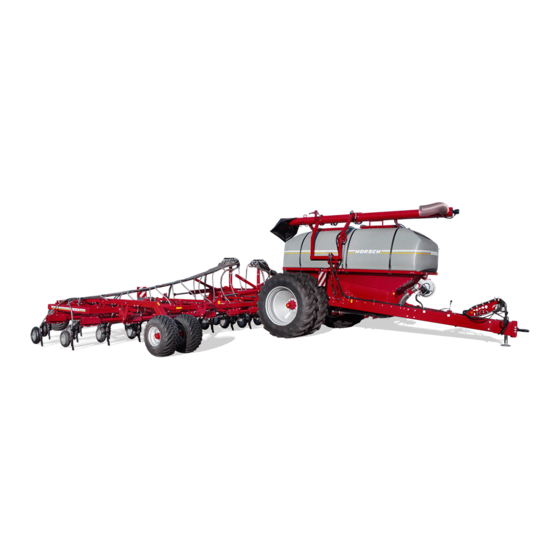
OPERATING INSTRUCTIONS
SPRINTER 11 / 15 NT
READ CAREFULLY PRIOR TO STARTING UP!
KEEP OPERATING INSTRUCTIONS IN A SAFE PLACE!
ART.:
80750202
ISSUE:
12/2015
Table of
Contents
Previous
Page
Next
Page
1
2
3
4
5
Advertisement
Table of Contents
Need help?
Do you have a question about the SPRINTER 11 NT and is the answer not in the manual?
Ask a question
Questions and answers
Related Manuals for horsch SPRINTER 11 NT
Farm Equipment horsch Terrano 10 FM Operating Instructions Manual
3 m (67 pages)
Farm Equipment horsch Maestro RV Series Operating Instructions Manual
(107 pages)
Farm Equipment horsch Terrano Series Operating Instructions Manual
(42 pages)
Farm Equipment horsch Maestro SW Series Owner's Manual
(68 pages)
Farm Equipment horsch Avatar 12.20 SW Operating Instructions Manual
(63 pages)
Farm Equipment horsch Transformer 6 VF Operating Instructions Manual
(92 pages)
Farm Equipment horsch Cruiser 10 XL Operating Instructions Manual
Grubber (71 pages)
Farm Equipment horsch Cruiser 10 XL Operating Instructions Manual
(102 pages)
Farm Equipment horsch Cruiser 12 XL Operating Instructions Manual
Grubber (71 pages)
Farm Equipment horsch Sprinter 18 NT Operating Instructions Manual
(62 pages)
Farm Equipment horsch Transformer 18 VF Operating Instructions Manual
Tool carrier (136 pages)
Farm Equipment horsch SPRINTER 15 NT Operating Instructions Manual
(55 pages)
Farm Equipment horsch Cultro 18 TC Operating Instructions Manual
(58 pages)
Farm Equipment horsch Maestro 12 SV Translation Of The Original Operating Instructions
(176 pages)
Farm Equipment horsch Maestro 18 SV Translation Of The Original Operating Instructions
(176 pages)
Farm Equipment horsch Maestro 12 SW Operating Instructions Manual
(90 pages)
This manual is also suitable for:
Sprinter 15 nt
35121253
35141280
Table of Contents
Print
Rename the bookmark
Delete bookmark?
Delete from my manuals?
Login
Sign In
OR
Sign in with Facebook
Sign in with Google
Upload manual
Upload from disk
Upload from URL


Need help?
Do you have a question about the SPRINTER 11 NT and is the answer not in the manual?
Questions and answers