Table of Contents
Advertisement
Quick Links
DCR822
Compact Dual Channel Digital Receiver
DCR822-A1B1, DCR822-B1C1, DCR822-941
Fill in for your records:
Serial Number:
Purchase Date:
INSTRUCTION MANUAL
Quick Start Summary
The following checklist includes the minimum required
settings to start using the receiver.
• Connect power to the receiver or install batteries
• Set the COMPAT (compatibility) mode for the trans-
mitters to be used
• Choose clean frequencies for your receiver chan-
nels using SmartTune or RF scan
• Set transmitters on the matching frequencies (see
transmitter manual) or use IR sync
• Verify transmitters are set to the same compatibility
mode as the receiver (see transmitter manual).
• Adjust transmitter input gain to match voice level
and mic position (see transmitter manual).
• Adjust receiver output level as needed for the
camera or mixer input level desired
• Turn on transmitter RF signals (see transmitter
manual)
Rio Rancho, NM, USA
www.lectrosonics.com
Advertisement
Table of Contents

Related Manuals for Lectrosonics DCR822


Summary of Contents for Lectrosonics DCR822
- Page 1 INSTRUCTION MANUAL DCR822 Compact Dual Channel Digital Receiver DCR822-A1B1, DCR822-B1C1, DCR822-941 Quick Start Summary The following checklist includes the minimum required settings to start using the receiver. • Connect power to the receiver or install batteries • Set the COMPAT (compatibility) mode for the trans- mitters to be used •...
- Page 2 DCR822 LECTROSONICS, INC.
-
Page 3: Table Of Contents
Power Input Jack ..............8 USB Port ................8 Battery Compartment............8 LCD Main Window..............9 Navigating the Menus ............9 DCR822 LCD Menu Map ............10 Menu Item Descriptions ............13 Recovering an Interrupted Recording .........16 Antenna Mounting and Orientation ........17 Antenna/Block Reference Table ..........19 Installation and Operating Instructions ......20 Finding Clear Frequencies ..........20... -
Page 4: General Technical Description
DCR822 General Technical Description DCR822 Block Diagram LECTROSONICS, INC. - Page 5 To assist in matching the audio levels of equipment con- receiver, to significantly reduce unwanted interfer- nected to the DCR822, a 1 kHz audio test tone, adjust- ence and intermodulation problems, the DCR822 has able from -50 to +7 dBu in 1 dB increments, is available a frequency selective front-end section that tracks at the outputs.
- Page 6 5 seconds, 30 seconds, or never. Recorder Function The DCR822 has a built in recording function for use in situations where the absolute minimum equipment is necessary, or as a backup to the main recorder system.
-
Page 7: Compatibility With Microsdhc Memory Cards
Dual Channel Digital Reciever Compatibility with microSDHC memory cards Please note that the DCR822 is designed for use with microSDHC memory cards. There are several types of SD card standards (as of this writing) based on capacity (storage in GB). -
Page 8: Front Panel Controls And Functions
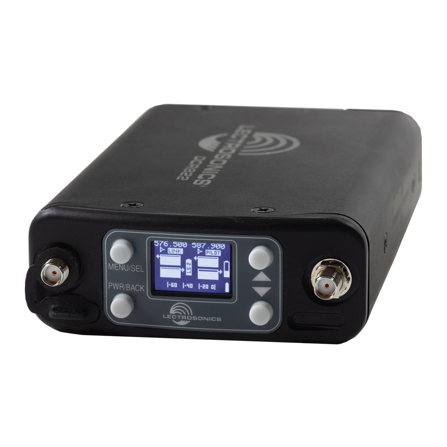
The unit is sent with a locking plug. USB Port The USB port can be used to connect the DCR822 to the Lectrosonics Wireless Designer software (pending). Battery Compartment Four AA batteries are installed as marked on the side panel of the receiver. -
Page 9: Lcd Main Window
Dual Channel Digital Reciever Main Window (LCD) The Main Window displays information concerning the MENU/SEL RF levels at each antenna per channel, the condition button of the Pilot Tone (Hybrid) or Link (digital), and battery conditions for both the receiver and the associated transmitters. -
Page 10: Dcr822 Lcd Menu Map
DCR822 DCR822 LCD Menu Map The menus presented on the LCD are arranged in a straightforward manner, with those that are likely to be used more often located at the top of the tree. Main Frequency Searching... TX1 Range Select option with arrow buttons RF Setup Selects open frequency. - Page 11 NORM NORM Dual Channel Digital Reciever Talkback Talkback to select. DCR822 LCD Menu Map Polarity Polarity to select. Files Files SD Card 0002. WAV to select. 0003. WAV Takes Takes 0002. WAV to select. 0003. WAV Record to stop/save Recording Scene &...
- Page 12 Get Frequency Get Freq to send key. get frequency DCR822 press menu/sel DCR822 LCD Menu Map Get Key Get All to get key. wipe key press menu/sel Select option with arrow buttons Key Type Key Type to select. Universal BACK...
-
Page 13: Menu Item Descriptions
DCR, and then sync the key with a transmitter. 1. Begin by selecting a key type. 2. The DCR822 will then display a warning to indicate that there is NO KEY! Select CREATE KEY to generate a new key. - Page 14 Allows user to turn off power to each receiver independently, while still allowing unit to function as a whole. RxBat Type: Allows the user to select the type of batteries used in the DCR822, giving the battery status indicator increased ac- curacy.
- Page 15 Lists files on the SD card in the Scenes and Takes format. Files are listed in the form of SXX TXXX. Selecting a file will display date, time, and length of recording. Record: Starts the DCR822 in recording mode, using the specified format in Settings>SD Card>File Naming. Record will change to Stop once recording has begun. Scene & Take: Allows user to set scene and take file naming starting point.
-
Page 16: Recovering An Interrupted Recording
If a recording is interrupted, all of the audio is present on the card and can be easily recovered by the DCR822. The DCR keeps track of the length of the most recent recording so it can supply a good suggestion for the length to recover. -
Page 17: Antenna Mounting And Orientation
Dual Channel Digital Reciever Antenna Mounting and AMJ Rev. A Jointed Antenna The AMJ-944 Rev. A antenna is a general purpose Orientation design with a hinged joint that pivots in both directions for positioning the whip at any desired angle. The pivot A variety of accessories are available to enable vari- allows the whips to be oriented vertically regardless of ous antenna mounting options. - Page 18 PCA900 COAXIAL CABLE ZSC24 SPLITTER Use Lectrosonics P/N 21770 BNC (F) to SMA (M) adapter; Pomona P/N 4290 STRONG SIGNAL The elements of both antennas should be parallel to each other for maximum signal strength. When they...
-
Page 19: Antenna/Block Reference Table
470.100 - 495.600 Black w/ Label 5.47” 141.2 mm 486.400 - 511.900 Black w/ Label 5.19” 133.9 mm Note: Not all Lectrosonics 512.000 - 537.500 Black w/ Label 4.95” 126.2 mm products are 537.600 - 563.100 Brown 4.73” 119.6 mm... -
Page 20: Installation And Operating Instructions
Normal levels should cause the DCR822’s audio level icon to fluc- The RF activity will be indicated by a vertical marker in tuate fully. This will result in the best possible signal the Scan Graph, as shown circled. -
Page 21: Firmware Update
In the DCR822: factory. 1) Leave the DCR822 turned off and insert the mi- • dcr822_boot vX_xx.hex is the bootloader file croSDHC memory card into the slot. Follow the same process as with a firmware update and 2) Hold down both the UP and DOWN arrow buttons select the dcr822boot file. -
Page 22: Diagnostics
Scanning with the RF spectrum analyzer built into the a clear frequency is found, turn the transmitter on DCR822 system will identify external RF signals, but and move on to the next channel. it does not address the compatibility of the selected frequencies. -
Page 23: Replacement Parts And Accessories
Dual Channel Digital Reciever Replacement Parts and Accessories CCMINI CCMINI Zip Pouch for Compact Wireless System 55010 Flash Memory Card, microSDHC memory card to SD Adapter Included AMJ22 Swivelling Whip Antenna with Standard SMA Con- nector, Available in Block 19 or 22. AMJ-XX Antenna with swiveling SMA connector 55010... -
Page 24: Troubleshooting
DCR822 Troubleshooting Symptom Possible Cause INITIAL POWER ON Display not active or lit. External power supply disconnected or inadequate. Main power supply fuse tripped. Turn the receiver off, remove the cause of the overload and turn the receiver back on. - Page 25 If the noise is still present, then the problem is not in the transmitter. If noise is still present when the transmitter is turned off, try lowering the audio output level on the DCR822 and see if the noise lowers correspondingly. If the noise remains, the problem is not in the receiver.
-
Page 26: Specifications And Features
Consult the dealer or an experienced radio/TV technician for help. External Power: Minimum 9 Volts to maximum 17 VDC Changes or modifications to this equipment not expressly approved by Lectrosonics, Inc. could 2.5 W; 170 mA at 12 VDC void the user’s authority to operate it. -
Page 27: Service And Repair
There are no adjustments inside that will make a malfunctioning unit start working. LECTROSONICS’ Service Department is equipped and staffed to quickly repair your equipment. In warranty repairs are made at no charge in accordance with the terms of the warranty. Out-of-warranty repairs are charged at a modest flat rate plus parts and shipping. - Page 28 DCR822 LECTROSONICS, INC.
- Page 29 Dual Channel Digital Reciever Rio Rancho, NM...
- Page 30 This warranty does not apply to used or demonstrator equipment. Should any defect develop, Lectrosonics, Inc. will, at our option, repair or replace any defective parts without charge for either parts or labor. If Lectrosonics, Inc. cannot correct the defect in your equipment, it will be replaced at no charge with a similar new item.
Need help?
Do you have a question about the DCR822 and is the answer not in the manual?
Questions and answers