Table of Contents
Advertisement
Quick Links
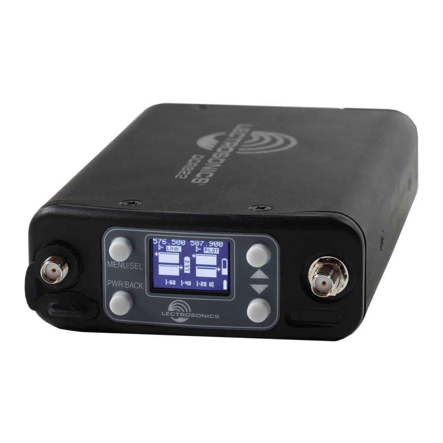
DCR822
Compact Dual Channel Digital Receiver
DCR822-A1B1, DCR822-B1C1, DCR822-941, DCR822-961
scan for informational
product video
Quick Start Summary
The following checklist includes the minimum required
settings to start using the receiver.
• Connect power to the receiver or install batteries.
• Set the COMPAT (compatibility) mode for the trans-
mitters to be used.
• Choose clean frequencies for your receiver chan-
nels using SmartTune or RF scan.
• Set transmitters on the matching frequencies (see
your transmitter manual) or use IR sync.
Fill in for your records:
Serial Number:
Purchase Date:
INSTRUCTION MANUAL
• Verify transmitters are set to the same compatibility
mode as the receiver (see your transmitter manual).
• Adjust transmitter input gain to match voice level
and mic position (see your transmitter manual).
• Select audio output type to match camera or mixer
input (analog or AES3 digital).
• Adjust receiver output level as needed for the
camera or mixer input level desired.
• Turn on transmitter RF signals (see your transmitter
manual).
Rio Rancho, NM, USA
www.lectrosonics.com
Advertisement
Table of Contents

Subscribe to Our Youtube Channel
Related Manuals for Lectrosonics DCR822


Summary of Contents for Lectrosonics DCR822
- Page 1 INSTRUCTION MANUAL DCR822 Compact Dual Channel Digital Receiver DCR822-A1B1, DCR822-B1C1, DCR822-941, DCR822-961 scan for informational product video Quick Start Summary The following checklist includes the minimum required • Verify transmitters are set to the same compatibility mode as the receiver (see your transmitter manual).
- Page 2 DCR822 LECTROSONICS, INC.
-
Page 3: Table Of Contents
Battery Compartment ..........7 LCD Main Window ............8 Navigating the Menus ..........8 Main Window Screens ..........8 Replacing the Batteries ..........9 DCR822 LCD Menu Map ..........10 Menu Item Descriptions ..........13 RF Setup ..............13 Tuning Groups............13 Using Diversity Modes ..........14 Audio Setup ..............15 Compat Mode............15... -
Page 4: General Technical Description
DCR822 DCR822 Block Diagram LECTROSONICS, INC. - Page 5 To assist in matching the audio levels of equipment con- and intermodulation problems, the DCR822 has a fre- nected to the DCR822, a 1 kHz audio test tone, adjustable quency selective front-end section that tracks and tunes from -50 to +7 dBu in 1 dB increments, is available at the to the desired signal frequency and rejects unwanted outputs.
-
Page 6: Compatibility With Microsdhc Memory Cards
5 seconds, 30 seconds, or never. Speed Class 10 Recorder Function The DCR822 has a built in recording function for use in situations where the absolute minimum equipment is necessary, or as a backup to the main recorder system. -
Page 7: Front Panel Controls And Functions
Rear Panel Features TA3 Audio Output Jacks USB Port The DCR822 uses a standard TA3 configuration with The microB USB port can be used to connect the pin 2 “positive.” The audio output is balanced but not DCR822 to the Lectrosonics Wireless Designer software floating, so an unbalanced signal is available using pin 1 (pending;... -
Page 8: Lcd Main Window
DCR822 LCD Main Window Antenna Transmitter 1 Frequency Frequency Status MENU/SEL Battery Status button 5 3 7 . 6 0 0 5 3 7 . 6 0 0 Channel Status L I N K L I N K Indicator ... -
Page 9: Replacing The Batteries
Dual Channel Digital Receiver Replacing the Batteries Lift the battery door to unlatch, push slightly forward and open it. Name Audio Level Observe the battery orientation markings on the side of the unit. Channel T x 1 L I N K Status indicator | - 6 0 | - 4 0 | - 2 0 0 |... -
Page 10: Dcr822 Lcd Menu Map
DCR822 DCR822 LCD Menu Map The menus presented on the LCD are arranged in a straightforward manner, with those that are likely to be used more often located at the top of the tree. Main Menu Tree Select option with arrow buttons... - Page 11 L T i m e 0 9 : 5 3 0 0 0 3 . W A V L e n 0 0 : 1 0 : 2 5 DCR822 LCD Menu Map Toggle with arrow buttons T a k e s...
- Page 12 BACK 3 0 S e c o n d s 5 S e c o n d s DCR822 LCD Menu Map Select option with arrow buttons R X P o w e r R X P o w e r to select.
-
Page 13: Menu Item Descriptions
If it is steady, it means that the currently tuned frequency is in the range, choose MENU/SEL and the DCR822 will search selected group. Choose No Group to exit the for a clear frequency. It will ask to sync. Press the DOWN... -
Page 14: Using Diversity Modes
DCR822 the frequency you wish to remove. Press the MENU/SEL • Four tuning groups are available, U, V, W, X, with and DOWN buttons together to delete that frequency each containing up to 32 frequencies that can be naed. Additionally, Compat Mode can be now cho- from the list. -
Page 15: Audio Setup
2. Connect a headphone amplifier to one of the audio outputs are routed, and to select how the TB signals in- outputs on the DCR822 (in Frequency Diversity teract with the normal program audio on those outputs. If mode, the resulting blended audio is mirrored on “Off”... -
Page 16: Sd Card Settings
If the length is ever unknown or the DCR822’s suggestion Takes: seems incorrect, it is always possible to override the sug- Lists files on the microSDHC card in the Scenes and gested length. -
Page 17: Ir & Keys Menu
If “No” is chosen, nothing is done to the card and the Send All DCR822 will not use the card. If “Yes” is chosen”, a prompt appears asking for the length of the recording (available only for digital compat modes) to recover, specified as a number of hours and minutes. -
Page 18: Encryption Key Management
The user Set the battery type for each transmitter channel. Note must select a key type and create a key in the DCR822, that for digital transmitters, the battery type is set in and then sync the key with the transmitter. -
Page 19: Antenna Mounting And Orientation
STRONG SIGNAL This setting restores the unit to factory settings. SIGNAL About Displays general information about the DCR822, in- cluding band, microcontroller and FPGA versions. The Fig. 3 microcontroller version number is the first number under Fig. 3 the band, followed by the FPGA version number after the WEAK forward slash. - Page 20 The SNA600a measures lower than a 2:1 SWR (Standing Wave Ratio) from 465 MHz to 850 MHz when the antenna arms are fully extended. Use Lectrosonics P/N 21770 BNC (F) to SMA (M) adapter; Pomona P/N 4290 Half-Power (-3 dB) Points Antenna Scale Center Frequency LECTROSONICS, INC.
-
Page 21: Antenna/Block Reference Table
64.3 mm 961.100 - 1014.900 Use antenna for 941 Note: Not all Lectrosonics products are built on all of the blocks covered in this chart. CUTTING TEMPLATE Lay uncut antenna on this template and cut to length for the desired frequency block... -
Page 22: Installation And Operating Instructions
If the output is too low, you may hear steady noise (hiss) along with the audio. The DCR822 audio output is designed to drive any audio input device from microphone level to +7dBu line level. If using AES3, the audio cannot be ad- justed. -
Page 23: Firmware Update
Follow the same process as with a firmware update and In the DCR822: select the DCR822boot file. 1) Leave the DCR822 turned off and insert the mi- NOTE: The ability to perform firmware updates croSDHC memory card into the slot. -
Page 24: Diagnostics
Scanning with the RF spectrum analyzer built into the signal is received. When a signal with the correct pilot DCR822 system will identify external RF signals, but it tone is received, the squelch opens and audio is deliv- does not address the compatibility of the selected fre- ered to the output. -
Page 25: Supplied Parts And Accessories
Supplied Parts and Accessories CCMINI 40073 Lithium Batteries Padded zipper pouch for handheld transmitter DCR822 is shipped with four (4) batteries. Brand may vary. 5510 Flash Memory Card, microSDHC memory card to SD Adapter Included. Brand and capacity may vary. - Page 26 DCR822 Optional Parts and Accessories MCSRXLR Audio output cable, TA3F Plug to XLRM, 12 in. SNA600A Omni Dipole Antenna Versatile Antenna, 100 MHz Bandwidth tunable from 550 to 800 MHz. Includes mounting screws and bracket. DCR12/A5U P1371 Power Supply, 110-240 VAC In, 12VDC Regulated Out, Replacement micro SDHC slot dust cover;...
-
Page 27: Troubleshooting
If the noise is still present, then the problem is not in the transmitter. If noise is still present when the transmitter is turned off, try lowering the audio output level on the DCR822 and see if the noise lowers correspondingly. If the noise remains, the problem is not in the receiver. -
Page 28: Specifications And Features
• SD Card Reader • Consult the dealer or an experienced radio/TV technician for help. • IR Port Changes or modifications to this equipment not expressly approved by Lectrosonics, Inc. could void the user’s authority to operate it. Rear Panel: •... -
Page 29: Service And Repair
There are no adjustments inside that will make a malfunctioning unit start working. LECTROSONICS’ Service Department is equipped and staffed to quickly repair your equipment. In warranty repairs are made at no charge in accordance with the terms of the warranty. Out-of-warranty repairs are charged at a modest flat rate plus parts and shipping. - Page 30 DCR822 LECTROSONICS, INC.
- Page 31 Dual Channel Digital Receiver Rio Rancho, NM...
- Page 32 This warranty does not apply to used or demonstrator equipment. Should any defect develop, Lectrosonics, Inc. will, at our option, repair or replace any defective parts without charge for either parts or labor. If Lectrosonics, Inc. cannot correct the defect in your equipment, it will be replaced at no charge with a similar new item.
Need help?
Do you have a question about the DCR822 and is the answer not in the manual?
Questions and answers