Table of Contents
Advertisement
Quick Links
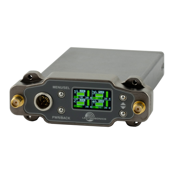
DSR4
Four Channel Digital Slot Receiver
DSR4-A1B1, DSR4-B1C1, DSR4-941, DSR4-961
• Four independent channels, compact
design
• Two diversity options for maximum
flexibility
• 24 bit/48 kHz digital for flawless audio
• AES 256-bit, CTR mode encryption, with
4 different key policies available
• High IP3 performance of +15 dBm for
tough RF environments
• Analog and AES3 digital audio outputs
• External DC powering options and USB
input for firmware updates and data
transfer
Fill in for your records:
Serial Number:
Purchase Date:
INSTRUCTION MANUAL
scan for informational
product video
Rio Rancho, NM, USA
www.lectrosonics.com
Advertisement
Table of Contents

Related Manuals for Lectrosonics DSR4


Summary of Contents for Lectrosonics DSR4
- Page 1 INSTRUCTION MANUAL DSR4 Four Channel Digital Slot Receiver DSR4-A1B1, DSR4-B1C1, DSR4-941, DSR4-961 • Four independent channels, compact design • Two diversity options for maximum flexibility • 24 bit/48 kHz digital for flawless audio • AES 256-bit, CTR mode encryption, with 4 different key policies available •...
- Page 2 • Consult the dealer or an experienced radio/TV technician for help. Changes or modifications to this equipment not expressly approved by Lectrosonics, Inc. could void the user’s authority to operate it. Installation & Operating Instructions The following checklist includes the minimum required settings to start using the receiver: •...
-
Page 3: Table Of Contents
IR & Keys Menu ............12 to use this receiver in-slot. Send Frequency ............12 Send All ..............12 The DSR4 is intended for use in slot Get Frequency ............12 devices which can supply enough current Get All ..............12 safely and without damage to fuses or Group Sync ..............12... -
Page 4: Dsr4 Block Diagram
DSR4 DSR4 Block Diagram LECTROSONICS, INC. -
Page 5: General Technical Description
RF signals from both channels, with differing phase angles in order to obtain maximum energy. The Audio Output Level four receivers in the DSR4 can be use separately or com- bined in pairs. A setup screen is provided for adjusting the audio output level in 1 dB increments from -50 to +7 dBu using the front panel MENU/SEL, UP, and DOWN buttons. -
Page 6: Installation & Operating Instructions
USB Port MENU/SEL Button (just under the front panel) The microB USB port can be used to connect the DSR4 The MENU button accesses the available menus and to the Lectrosonics Wireless Designer software and to selects the desired setting. -
Page 7: Main Window Display
Four Channel Digital Receiver Menu Item Descriptions Main Window Display Channel RF Setup Status Antenna Indicator Channel Status Smart Tune Channel Smart Tune is the easiest and fastest way to scan the local RF spectrum and find clear operating frequencies. The receiver will scan through the selected tuning band- width and automatically find “empty”... -
Page 8: Dsr4 Lcd Menu Map
DSR4 DSR4 LCD Menu Map The menus presented on the LCD are arranged in a straightforward manner, with those that are likely to be used more often located at the top of the tree. The menu headers are now in color, with symbols indicative of the menu section. Paging through the tree, the heading bar of each individual submenu choice corresponds to the color of the category it resides in. - Page 9 P o l a r i t y Four Channel Digital Receiver P O S P O S DSR4 LCD Menu Map Select Rx1-4 with arrow buttons C o m p a t M o d e C o m p a t...
-
Page 10: Frequency
NOTE: A convenient shortcut from any other zoom in and see a smaller (about 20 MHz) section of the menu or page in the DSR4 directly to the scan results. Pressing UP+DOWN again zooms out to Frequency page is to press the UP and Down the full scan view. -
Page 11: Group Edit
MENU/SEL fixed on Antenna A and the other receiver in a pair is button then press the UP or DOWN buttons. fixed on Antenna B. The DSR4 automatically and opti- mally combines the intermediate frequency signals. Clear Scan: Clears scan results. -
Page 12: Output Type
NOTE: You must position the transmitter’s IR • Universal: This is the most convenient and basic port directly in front of the DSR4 IR port, as option available, and the default setting on all closely as possible, to guarantee a successful Lectrosonics D2 digital units. -
Page 13: Encryption Keys
The user must Tx Batt Timer select a key type and create a key in the DSR4, and then Choose between Bar, Volt or Time. Use MENU/SEL to sync the key with the transmitter. -
Page 14: Default
About of the orientation of the receiver. Displays general information about the DSR4 , including Maximum sensitivity is perpendicular to the whip, so band, microcontroller and FPGA versions. The microcon- an ideal setup is shown in Fig. 1 and Fig. 2 where the... - Page 15 ZSC24 SPLITTER Half-Power (-3 dB) Points Center Frequency Use Lectrosonics P/N 21770 BNC (F) to SMA (M) adapter; Pomona P/N 4290 AMJ Jointed Antenna The AMJ antenna is a general purpose design with a hinged joint that pivots in both directions for positioning the whip at any desired angle.
-
Page 16: Firmware Update Instructions
Firmware Update Instructions Firmware updates are made through Wireless Desiger, with a file downloaded from the web site and the DSR4 connected via USB. The USB port on the receiver re- quires a micro-B male plug on the connecting cable. The... -
Page 17: Antenna/Block Reference Table
Black w/Label 2.53” 64.3 mm Note: Not all Lectrosonics products are built on all of the blocks covered in this chart. CUTTING TEMPLATE Lay uncut antenna on this template and cut to length for the desired frequency block Whip Length... -
Page 18: Diagnostics
Scanning with the RF spectrum analyzer built into the a clear frequency is found, turn the transmitter on DSR4 system will identify external RF signals, but it does and move on to the next channel. not address the compatibility of the selected frequen- cies. -
Page 19: Supplied Parts And Accessories
AMJ19 Swivelling Whip Antenna with Standard SMA Connector, Block 19. Ships with A1B1 units only. 28979 Replacement screws (4) for 36016 DSR4 mounting bezel AMJ22 kit. Swivelling Whip Antenna with Standard SMA Connector, Block 22. Ships with A1B1 and B1C1 units. -
Page 20: Aligning Specialty Adapters
Power cord not included; order PS200A or use equivalent. DSR4OCTOSPACER DSR4 mounting bezel (bezel is P/N 36016) kit with 4 screws (P/N 28979) for Octopack and Quadpack, no WARNING: Do not use Hirose connector included. - Page 21 Four Channel Digital Receiver MCSR/5PXLR2 Audio cable for SR-type receivers, rotatable right-angle TA5 to two 3-pin male XLRs. 20” cable. PS200A Power Cable, 15 in., Hirose4 to LZR PS2200A Power Cable, 15 in., Hirose4 to Dual LZR SNA600A Omni Dipole Antenna Versatile Antenna, 100 MHz Bandwidth tunable from 550 to 800 MHz.
-
Page 22: Ir Reflector: Purpose And Installation
DSR4. reflector allows IR sync to happen from the front of the control panel. Materials Needed: 5) Lay the DSR4 on a flat surface with adhesive facing up, and, using your tweezers, align the bottom edge of IR Reflector ... -
Page 23: Specifications And Features
Four Channel Digital Receiver Specifications and Features Operating Frequencies (MHz): External Power: Minimum 9 Volts to maximum 17 VDC 4.1 W; 340 mA at 12 VDC Model A1B1: 470.100 - 614.375 Model B1C1: 537.600 - 691.175 Operating Temp. Range: -20 to 40°C; -5 to 104°F 941: 941.525 - 959.825 Weight:... -
Page 24: Troubleshooting
DSR4 Troubleshooting Symptom Possible Cause INITIAL POWER ON Display not active or lit. External power supply disconnected or inadequate. Main power supply fuse tripped. Turn the receiver off, remove the cause of the overload and turn the receiver back on. -
Page 25: Service And Repair
LECTROSONICS’ Service Department is equipped and staffed to quickly repair your equipment. In warranty repairs are made at no charge in accordance with the terms of the warranty. Out-of-warranty repairs are charged at a modest flat rate plus parts and shipping. - Page 26 DSR4 LECTROSONICS, INC.
- Page 27 Four Channel Digital Receiver Rio Rancho, NM...
- Page 28 This warranty does not apply to used or demonstrator equipment. Should any defect develop, Lectrosonics, Inc. will, at our option, repair or replace any defective parts without charge for either parts or labor. If Lectrosonics, Inc. cannot correct the defect in your equipment, it will be replaced at no charge with a similar new item.
Need help?
Do you have a question about the DSR4 and is the answer not in the manual?
Questions and answers