
Subscribe to Our Youtube Channel
Related Manuals for Lectrosonics D4


Summary of Contents for Lectrosonics D4
- Page 1 INSTRUCTION MANUAL Digital Wireless System Fill in for your records: Serial Number: Purchase Date: Rio Rancho, NM, USA www.lectrosonics.com...
- Page 2 D4T/D4R LECTROSONICS, INC.
-
Page 3: Table Of Contents
• Digital in/Analog out • Analog in/Digital out • Analog in/Analog out In the 4-channel mode, the D4 system operates on one of four 4 MHz channels in the 902 to 928 MHz band. Each channel carries four separate audio signals, digitally multiplexed on a common carrier. -
Page 4: General Technical Description
24-bit D/A (analog) AES/EBU (digital) TA3M INPUTS DIGITAL 24-bit D/A BASEBAND (analog) ENCODER AES/EBU (digital) CIRCULATOR ISOLATOR 24-bit D/A (analog) 24-bit D/A (analog) FILTER POWER 900 MHz LECTROSONICS, INC. -
Page 5: D4R Receiver
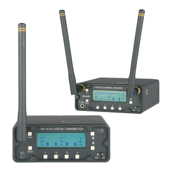
4-channel Digital Wireless System D4R Receiver The receiver employs two complete RF sections for true diversity reception. The signals from both anten- nas are independently decoded and error-corrected, and the diversity system uses all digital data and tim- ing reference information from both antennas in order to reconstruct the original audio signals. -
Page 6: Front And Rear Panels
3-4 (pair) for stereo monitoring 2/4 CHANNEL DIGITAL RECEIVER 9-16 VDC AES IN AES IN 500mA CH1/CH2 CH3/CH4 9-16 VDC AES OUT AES OUT 250mA CH1/CH2 CH3/CH4 The Main Window will indicate possible clipping on the bar graph on both units. LECTROSONICS, INC. -
Page 7: Navigating The Lcd
4-channel Digital Wireless System Navigating the LCD Navigation through setup screens is the same on the transmitter and receiver. The Main Window will display audio levels for all active channels while the system is operating. Press the FUNC button to enter the setup menu. DIGITAL 4 CHANNEL TRANSMITTER FUNC BACK... -
Page 8: Transmitter General Settings
AES3 Mode selection. See buttons to select the next page for details. desired mode AES3 Modes Use UP/DOWN arrows to select menu item and press FUNC to enter setup Use UP/DOWN buttons to select desired mode LECTROSONICS, INC. -
Page 9: Transmitter Audio Trim Setup
4-channel Digital Wireless System Transmitter Audio Trim Setup From the Main Window, press FUNC and then select The analog inputs are designed for line level signals. the menu item “Audio Trim” and press FUNC again. There is no gain stage in the input section. Attenua- The setup screen will vary slightly depending upon tion up to 20 dB can be applied to the input signal to which AES3 mode has been selected and whether... -
Page 10: Receiver General Settings
(highlighted) channel only, at the level shown. Use UP/DOWN arrows to select menu item and press FUNC to enter setup Press the button under the analog channel to be adjusted and then use the UP and DOWN buttons to set the desired level. LECTROSONICS, INC. -
Page 11: Receiver Audio Level Setup
4-channel Digital Wireless System Receiver Locked/Unlocked Modes The front panel controls can be locked to prevent Audio Level Setup inadvertent changes in the selected settings. When the panel is Locked, settings can be viewed but not changed, with the exception of headphone selection From the Main Window, press FUNC and then select and monitoring level controls. -
Page 12: Transmitter Input Modes
Two different configurations are available for 2-channel operation: DIGITAL CH 1 CH 1 ANALOG DIGITAL CH 2 CH 2 ANALOG NOT USED CH 3 NOT USED CH 3 NOT USED CH 4 NOT USED CH 4 NOT USED LECTROSONICS, INC. -
Page 13: Antenna Placement And Orientation
4-channel Digital Wireless System Antenna Placement and Frequency Selection Orientation It is best to check for interference before selecting a channel. Turn the receiver on and leave the transmitter off. Observe the RF level indicator in the Main Window The supplied antenna is a center fed half-wave type to see if signal is present. -
Page 14: Parts And Accessories
100-240 VAC, 50/60 Hz, 1.6 A (max) input; 13.8 VDC, 2.8A, 40 W (max) output. (Includes 21499 AC power cord) AC Power Cord • Lectrosonics 21499 Power Cord. NEMA 5-15 plug (USA); for use with PS70 and DCR15/1A6U LECTROSONICS, INC. - Page 15 4-channel Digital Wireless System Power Adapter Cables Antenna • Lectrosonics 21747 right angle, locking plug with 6 • Lectrosonics 21422 center fed, half wave anten- ft. cable to stripped and tinned leads. Supplied with na. Supplied with transmitter and receiver.
-
Page 16: Specifications
Audio Output: Electronically balanced outputs, clip level adjustable –20 to +8 dBu (or AES/EBU digital standard) Power requirements: 9 - 16 VDC Power consumption: 250 mA Dimensions: 4 x 4 x 1.5 inches Weight: 346 grams; 12.2 ozs. LECTROSONICS, INC. - Page 17 If this equipment does cause ohms. harmful interference to radio or television reception, Lectrosonics P/N 21422 center fed half wave antenna which can be determined by turning the equipment off and on, the user is encouraged to try to correct the...
-
Page 18: Service And Repair
There are no adjustments inside that will make a malfunctioning unit start working. Lectrosonics’ Service Department is equipped and staffed to quickly repair your equipment. In warranty repairs are made at no charge in accordance with the terms of the warranty. Out-of-warranty repairs are charged at a mod- est flat rate plus parts and shipping. - Page 20 This warranty does not apply to used or demonstrator equipment. Should any defect develop, Lectrosonics, Inc. will, at our option, repair or replace any defective parts without charge for either parts or labor. If Lectrosonics, Inc. cannot correct the defect in your equipment, it will be replaced at no charge with a similar new item.
Need help?
Do you have a question about the D4 and is the answer not in the manual?
Questions and answers