Table of Contents
Advertisement
Quick Links
Advertisement
Table of Contents

Related Manuals for RGBlink MSP 329


Summary of Contents for RGBlink MSP 329
- Page 1 MSP 329 USER MANUAL Article No: RGB-RD-UM-MSP329 E001 Revision No: V1.0...
-
Page 2: Table Of Contents
CONTENTS CONTENTS................................ 1 Declarations..............................2 FCC/Warranty............................2 Operators Safety Summary........................3 Installation Safety Summary........................3 Chapter 1 Your Product............................ 5 1.1 Product Overview..........................5 1.2 Front Panel............................6 1.3 Rear Panel............................8 1.4 Dimension............................12 Chapter 2 Install Your Product........................13 2.1 Plug in Signals..........................13 2.2 Plug in Main Power.......................... -
Page 3: Declarations
30 days after the transfer of risks. In the event of justified notice of compliant, RGBlink can repair the fault or provide a replacement at its own discretion within an appropriate period. If this measure proves to be impossible or unsuccessful, the purchaser can demand a reduction in the purchase price or cancellation of the contract. -
Page 4: Operators Safety Summary
Operators Safety Summary The general safety information in this summary is for operating personnel. Do Not Remove Covers or Panels There are no user-serviceable parts within the unit. Removal of the top cover will expose dangerous voltages. To avoid personal injury, do not remove the top cover. Do not operate the unit without the cover installed. - Page 5 Unpacking and Inspection Before opening MSP329 processor shipping box, inspect it for damage. If you find any damage, notify the shipping carrier immediately for all claims adjustments. As you open the box, compare its contents against the packing slip. If you find any shortages, contact your sales representative. Once you have removed all the components from their packaging and checked that all the listed components are present, visually inspect the system to ensure there was no damage during shipping.
-
Page 6: Chapter 1 Your Product
Chapter 1 Your Product 1.1 Product Overview MSP329 provides the flexible, powerful, and scalable solution at resolutions up to 3840 x 2160@60Hz 4:2:0, 3840 x 2160@30Hz 4:4:4. They allow 4K UHD media to be switched and distributed over standard gigabit Ethernet networks, providing complete end-to-end streaming systems. -
Page 7: Front Panel
POWER MSP 329 TX is powered on. Indicator MSP 329 TX is powered off. MSP 329 TX is connected to both an active video source and MSP Solid On 329 RX. MSP329 TX is disconnected from an active video source. - Page 8 MSP329 RX Name Description MSP329 RX is powered on. POWER Indicator MSP329 RX is powered on. MSP329 RX is connected to MSP329 TX and the video is Solid On displayed. MSP329 RX is disconnected from MSP329 TX. Blinking STATUS MSP329 RX is disconnected from an active video source.
-
Page 9: Rear Panel
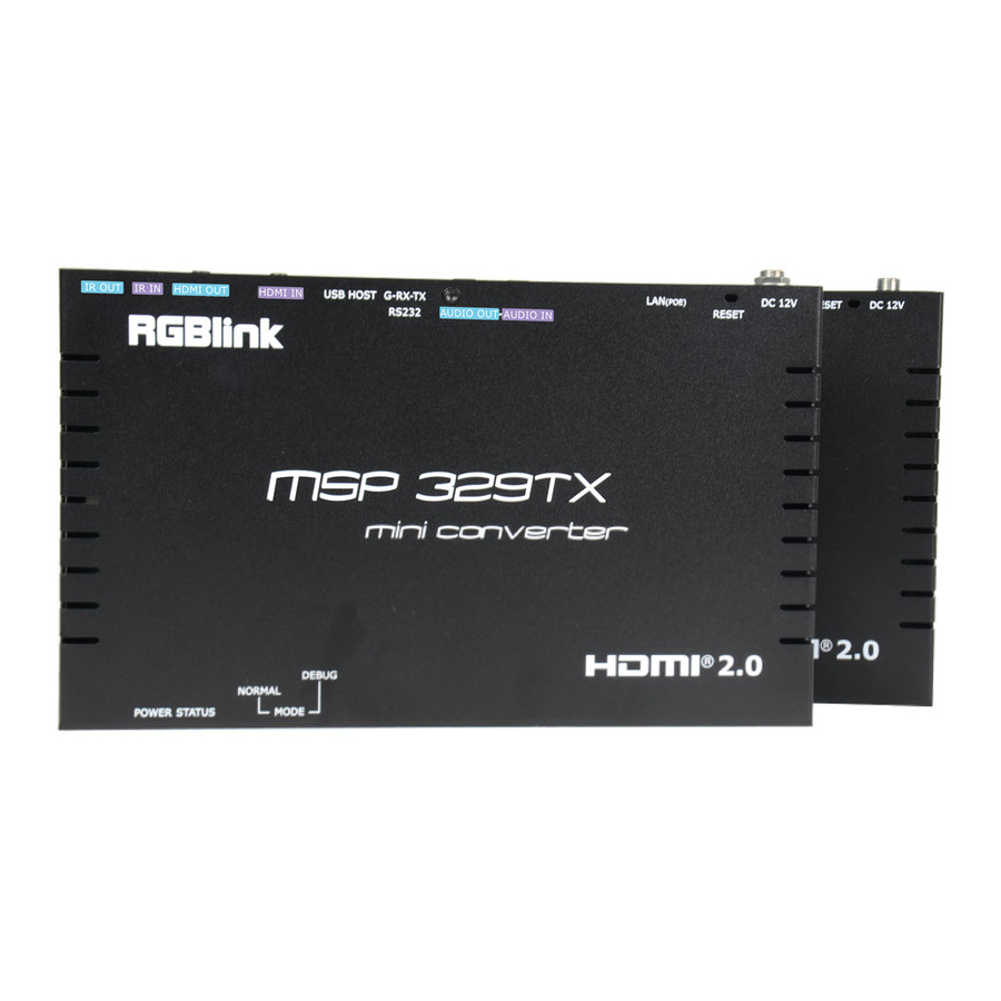
1.3 Rear Panel MSP329 TX Name Description IR OUT: connect this 3.5 mm tip-sleeve port to an IR emitter for IR communication with an IR receiver in the MSP329 RX side on the network. IR Emitter: IR Output Note: This IR cable illustration applies to the IR output ports in MSP329 TX and MSP329 RX. - Page 10 Name Description Communication device debug functions. When the front panel "MODE" switch is moved to the "NORMAL" position, connect this port to a RS232 device such as a computer to bi-directionally communicate with a RS232 device at the IP controller side.
- Page 11 Name Description the RJ-45 port, eliminating the need for a nearby power outlet. Power supply via a power adapter has higher priority as compared to PoE power supply. When the device is connected to both the supplied power adapter and the PoE-enabled Ethernet switch, it receives power from the power adapter instead of the switch.
- Page 12 Name Description AUDIO OUT: connect this 3.5 mm stereo tip-ring-sleeve port to an audio output device such as a speaker and an amplifier to output Audio Output unbalanced, stereo audio signals. LAN (POE): 10/100/1000 Base-T port, connect this port to a gigabit Ethernet switch for IP stream input, device control and device management.
-
Page 13: Dimension
1.4 Dimension Following is the dimension of MSP329 for your reference: MSP329 TX: 220mm×130mm×25mm MSP329 RX:220mm×130mm×25mm MSP329 User Manual... -
Page 14: Chapter 2 Install Your Product
Chapter 2 Install Your Product 2.1 Plug in Signals Connect input and output signals with USB or HDMI cables to the MSP329 RX/TX,and connect RX/TX to switcher with Cat6 before all devices are powered on. Huawei Switchers such as S5720S-28P-PWR-LI-AC and S5720S-52P-PWR-LI-AC are recommended. 2.2 Plug in Main Power Connect MSP329 RX/TX to the power with power adapter. -
Page 15: Chapter 3 Use Your Product
Chapter 3 Use Your Product Introduction to Different Operation Tools The MSP329 RX/TX allow you to use the front panel link DIP switch, PC configurator, VisualM and IP controller to manage and control the encoders and decoders. This section briefly introduces how to route the video from source to the display using these tools. -
Page 16: Dip Switch For Perform Routing
DIP Switch for Perform Routing Before using the DIP switch, check that routing operations were not performed by other the tools. Otherwise, the switch function is disabled. If so, press and hold the rear panel RESET button in decoder for less than five seconds to enable the DIP switch. To route the video from source to display, toggle each individual switches of the front panel DIP switch in decoder to the same positions as these in encoder. - Page 17 2. Parameter Modification of TX/RX Click Batch Commands > IP > Static and change IP address. Click Video > For JPEG 2000 MSP329 supports HDR10 only if the HDMI Timing Hybrid is set to “Pass-through” mode (default setting). Note : Reboot the devices configured for the new settings to take effect. MSP329 User Manual...
- Page 18 Click Video > For H.264 and modify video parameters Output Resolutions: 800×600@60 | 1024×768@60 | 1280×720@60 | 1280×1024@60 | 1360 ×768@60 | 1440×900@60 | 1440×1050@60 | 1600×1200@60 | 1920×1080@60 | 3840× 2160@30 Click Video > For SDVoE and modify Input, Support HDCP, Video Mode,etc. MSP329 User Manual...
- Page 19 Click Image and upload Idle Image, Power on Logo Image and Overlay Image. Click Audio and select analogy direction and source MSP329 User Manual...
- Page 20 Click Serial and modify Baud Rate, Data Bits, Stop Bits and Parity. Click Power and modify CEC and RS232 Settings MSP329 User Manual...
- Page 21 Click EDID and select EDID file Click Advanced and select Video over IP/Audio over IP/USB over IP/KM over IP/Serial over IP/IR over MSP329 User Manual...
- Page 22 Click Others and select Reboot or Reset to Factory 3. Create a video wall. Click ungrouped in the RX list > Create VW > Name a video wall VW and choose rows and columns > OK. MSP329 User Manual...
- Page 23 4. Create a layout for the video wall. Click VW in the RX list > Create Layout/Scene in the working area > name this layout layout1 and choose Standard Video Wall > OK. Users can choose Layout/Scene Type: Standard Video Wall Video Wall within a Wall PIP/Widowing Processor Mouse Roaming...
- Page 24 6. Configure Master and Slave. Right click the RX to which the mouse and keyboard are connected and choose Select Master > right click the other one and choose Select Slave > Click Apply > OK. Note: To cancel Select Master/Select Slave setting, right click on the RX and choose Delete Master/Delete Slave.
- Page 25 MSP329 User Manual...
-
Page 26: Chapter 4 Ordering Codes
Chapter 4 Ordering Codes 4.1 Product 611-0329-01-0 MSP329(TX) 611-0329-02-0 MSP329(RX) MSP329 User Manual... -
Page 27: Chapter 5 Support
Chapter 5 Support 5.1 Contact Us MSP329 User Manual... -
Page 28: Chapter 6 Appendix
Chapter 6 Appendix 6.1 Terms & Definitions ●RCA:Connector used primarily in consumer AV equipment for both audio and video. The RCA connector was developed by the Radio Corporation of America. ●BNC: Stands for Bayonet Neill-Concelman. A cable connector used extensively in television (named for its inventors). - Page 29 the ultra high definition signal/data interface (U-SDI) for transmitting 4K and 8K signals using a single optical cable. The interface was standardized as the SMPTE ST 2036-4. ●HDMI : High Definition Multimedia Interface: An interface used for the transmission of uncompressed high definition video, up to 8 channels of audio, and control signals, over a single cable.
- Page 30 ●Multi-mode Fiber: Fibers that support many propagation paths or transverse modes are called multi-mode fibers, generally have a wider core diameter and are used for short-distance communication links and for applications where high power must be transmitted. ●Single-mode Fiber: Fiber that support a single mode are called single-mode fibers. Single-mode fibers are used for most communication links longer than 1,000 meters (3,300 ft).
- Page 31 Type Type B Mini Mini Micro- Micro Type C USB 2.0 USB 3.0 3.1&3.2 ●NTSC : The colour video standard used in North America and some other parts of the world created by the National Television Standards Committee in the 1950s. NTSC utilizes an interlaced video signals.
- Page 32 commonly used in integration applications. ●Dante AV: The Dante protocol was developed for and widely adopted in audio systems for the transmission of uncompressed digital audio on IP based networks. The more recent Dante AV specification includes support for digital video. ●NDI: Network Device interface (NDI) is a software standard developed by NewTek to enable video-compatible products to communicate, deliver, and receive broadcast quality video in a high quality, low latency manner that is frame-accurate and suitable for switching in a live production environment...
- Page 33 ●MIDI: MIDI is the abbreviation of Musical Instrument Digital Interface. As the name indicates the protocol was developed for communication between electronical musical instruments and latterly computers. MIDI instructions are triggers or commands sent over twisted pair cables, typically using 5pin DIN connectors.
- Page 34 ●Colour Bars: A standard test pattern of several basic colours (white, yellow, cyan, green, magenta, red, blue, and black) as a reference for system alignment and testing. In NTSC video, the most commonly used colour bars are the SMPTE standard colour bars. In PAL video, the most commonly used colour bars are eight full field bars.
-
Page 35: Revision History
6.2 Revision History The table below lists the changes to the Video Processor User Manual. Format Time ECO# Description Principal V1.0 2020-12-23 0000# Release Sylvia MSP329 User Manual...
Need help?
Do you have a question about the MSP 329 and is the answer not in the manual?
Questions and answers