Advertisement
Advertisement
Table of Contents

Related Manuals for Yeastar Technology P Series


Summary of Contents for Yeastar Technology P Series
- Page 1 Installation Guide Yeastar P-Series PBX System blank Installation Guide Version: 1.0 Date: 2020-12-08...
-
Page 2: Table Of Contents
Contents About this Guide........................1 Hardware Overview......................2 Yeastar P550 Overview....................2 Yeastar P560 Overview....................4 Yeastar P570 Overview....................6 Expansion Board......................7 Install PBX...........................10 Installation Warnings..................... 10 Package Contents......................10 Install Yeastar P550......................11 Install Yeastar P560......................16 Install Yeastar P570......................23 Connect Your PBX...................... -
Page 3: About This Guide
About this Guide This guide describes hardware ports and indicators on Yeastar P-Series PBX System, gives instructions on how to install the PBX and telephony modules, and quickly log in to the PBX web interface. Product covered • Yeastar P550 •... -
Page 4: Hardware Overview
Hardware Overview Yeastar P550 Overview Front panel Table 1. Feature Description NFC Tag Tap NFC-capable mobile phone's back against Yeastar logo to quickly configure network settings. System Indicator Indicate the system status. • Blinking: The system is working properly. • Static/Off: The system goes wrong. Power Indicator Indicate the power status. - Page 5 Installation Guide | 2 - Hardware Overview | 3 Table 1. (continued) Feature Description • BRI: # Orange: blinking: The BRI line is disconnected. # Orange: static: The BRI line is connected or in use. • FXO: # Red: static: The PSTN line is idle. # Red: blinking slowly: No PSTN line is connected to the FXO port.
-
Page 6: Yeastar P560 Overview
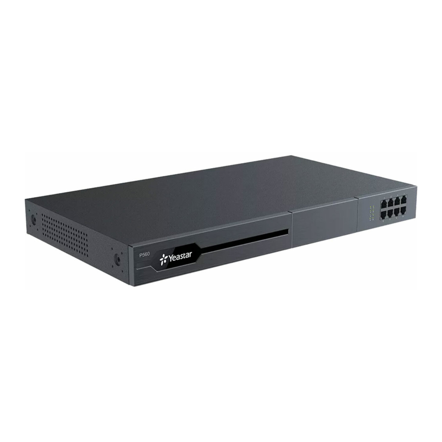
Installation Guide | 2 - Hardware Overview | 4 Yeastar P560 Overview Front panel Yeastar P560 supports 1 expansion board. You can install either EX08 board or EX30 board according to your needs. Figure 1.Yeastar P560 front panel with an EX08 expansion board Figure 2.Yeastar P560 front panel with an EX30 expansion board Table 3. - Page 7 Installation Guide | 2 - Hardware Overview | 5 Rear panel Table 4. Feature Description Reset button Press the button to restore to factory defaults. System Indicator Indicate the system status. • Blinking: The system is working properly. • Static/Off: The system goes wrong. Power Indicator Indicate the power status.
-
Page 8: Yeastar P570 Overview
Installation Guide | 2 - Hardware Overview | 6 Yeastar P570 Overview Front panel Table 5. Description NFC tag. Tap NFC-capable mobile phone's back against Yeastar logo to quickly configure network settings. EX30 Expansion Board, which is used to connect an E1/T1/J1 line. EX08 Expansion Board. -
Page 9: Expansion Board
Installation Guide | 2 - Hardware Overview | 7 Table 6. (continued) Feature Description • Static/Off: The system goes wrong. Power Indicator Indicate the power status. SD Slot Insert an SD card to store recording files, voicemails, or logs. USB Slot Insert a USB flash drive to storage recording files, voicemails, or logs. - Page 10 Installation Guide | 2 - Hardware Overview | 8 Optional modules on EX08 board • O2 Module • S2 Module • SO Module • B2 Module • GSM/3G/4G LTE Module EX30 Expansion Board EX30 board supports 1 E1/T1/J1 port. D30 Module D30 is a DSP module, used to expand the capacity of PBX.
- Page 11 Installation Guide | 2 - Hardware Overview | 9...
-
Page 12: Install Pbx
Install PBX Installation Warnings To avoid unexpected accident, personal injury, or device damage, read the safety dis- claimers and installation warnings. Power Safety • Use only the power cord provided with the PBX. • Keep the power off during installation. •... -
Page 13: Install Yeastar P550
Installation Guide | 3 - Install PBX | 11 Package Contents of P560 • 1* Yeastar P560 Appliance • 1* Power Cord • 1* Ethernet Cable • 2* Rack Mounting Kits • 1* Grounding Stud & Nut • 4* Rubber Feet •... - Page 14 Installation Guide | 3 - Install PBX | 12 2. Insert the module to the Module Slot. 3. Follow the instructions to insert a SIM card on the GSM/3G/4G LTE module. Note: Skip this step if no GSM/3G/4G LTE module is installed.
- Page 15 Installation Guide | 3 - Install PBX | 13 4. Close the cover and fix the screws. 5. Rotate the antenna into the Antenna Socket. Note: Skip this step if no GSM/3G/4G LTE module installed. Desktop Installation CAUTION: • Set 5~10cm gaps around the device for air circulation. •...
- Page 16 Installation Guide | 3 - Install PBX | 14 Rack Installation CAUTION: • Be careful not to drop any components. Dropping components may damage them or cause an injury. • Only use the 19-inch rack mounting kits (attached bracket and fittings) included with the PBX.
- Page 17 Installation Guide | 3 - Install PBX | 15 Ground Connection CAUTION: • Proper grounding (connection to ground) is very important to reduce the risk of elec- trocution to the user or protect the PBX from bad effects of external noise in case of a lightning strike.
-
Page 18: Install Yeastar P560
Installation Guide | 3 - Install PBX | 16 Install Yeastar P560 Install Telephony Module Yeastar P560 supports the followings: • Max. 1 EX08 Expansion Board • Max. 1 EX30 Expansion Board • Max. 4 Telephony Module • Max. 1 D30 Module The optional telephony modules are as below: •... - Page 19 Installation Guide | 3 - Install PBX | 17 1. Loosen the screws at the bottom of the device and remove the upper cover. 2. Push out the empty board from the inside of the device. 3. Push in the Expansion Board (EX08 or EX30).
- Page 20 Installation Guide | 3 - Install PBX | 18 4. Lock the screws to fix the Expansion Board. 5. Insert the Telephony Modules on the EX08 Board. Note: Skip this step for EX30 Board. 6. Follow the instructions to insert a SIM card on the GSM/3G/4G LTE module.
- Page 21 Installation Guide | 3 - Install PBX | 19 Note: Skip this step if no GSM/3G/4G LTE module is installed. 7. Close the cover and fix the screws. 8. Rotate the antenna into the Antenna Socket. Note: Skip this step if no GSM/3G/4G LTE module installed.
- Page 22 Installation Guide | 3 - Install PBX | 20 Install DSP Module 1. Open the device upper cover and insert the DSP module (D30) into the D-Slot from a tilt angle and then press it down. 2. Lock the screws to fix the D30 module board. Desktop Installation CAUTION: •...
- Page 23 Installation Guide | 3 - Install PBX | 21 Rack Installation CAUTION: • Be careful not to drop any components. Dropping components may damage them or cause injury. • Only use the 19-inch rack mounting kits (attached bracket and fittings) included with the PBX.
- Page 24 Installation Guide | 3 - Install PBX | 22 Ground Connection CAUTION: • Proper grounding (connection to ground) is very important to reduce the risk of elec- trocution to the user or protect the PBX from bad effects of external noise in case of a lightning strike.
-
Page 25: Install Yeastar P570
Installation Guide | 3 - Install PBX | 23 Install Yeastar P570 Install Telephony Module Yeastar P570 supports the followings: • Max. 2 EX08 Expansion Board • Max. 2 EX30 Expansion Board • Max. 8 Telephony Module • Max. 2 D30 Module The optional telephony modules are as below: •... - Page 26 Installation Guide | 3 - Install PBX | 24 Note: Before installing the module, check if the module is clean and intact. 1. Loosen the screws at the bottom of the device and remove the upper cover. 2. Push out the empty board from the inside of the device. 3.
- Page 27 Installation Guide | 3 - Install PBX | 25 4. Lock the screws to fix the Expansion Board. 5. Insert the Telephony Modules on the EX08 Board. Note: Skip this step for EX30 Board. 6. Follow the instructions to insert a SIM card on the GSM/3G/4G LTE module. Note: Skip this step if no GSM/3G/4G LTE module is installed.
- Page 28 Installation Guide | 3 - Install PBX | 26 7. Close the cover and fix the screws. 8. Rotate the antenna into the Antenna Socket. Note: Skip this step if no GSM/3G/4G LTE module installed.
- Page 29 Installation Guide | 3 - Install PBX | 27 Install DSP Module 1. Open the device upper cover and insert the DSP module (D30) into the D-Slot from a tilt angle and then press it down. 2. Lock the screws to fix the D30 module board. Desktop Installation CAUTION: •...
- Page 30 Installation Guide | 3 - Install PBX | 28 Rack Installation CAUTION: • Be careful not to drop any components. Dropping components may damage them or cause injury. • Only use the 19-inch rack mounting kits (attached bracket and fittings) included with the PBX.
- Page 31 Installation Guide | 3 - Install PBX | 29 Ground Connection CAUTION: • Proper grounding (connection to ground) is very important to reduce the risk of elec- trocution to the user or protect the PBX from bad effects of external noise in case of a lightning strike.
- Page 32 Installation Guide | 3 - Install PBX | 30...
-
Page 33: Connect Your Pbx
Connect Your PBX Connect your PBX to the local network, and connect telephony lines to the PBX. 1. Connect your PBX to the network. Connect one end of an Ethernet cable to the LAN port of your PBX, and the other end to any port of your company’s LAN switch/router. -
Page 34: Change The Ip Address Of The Pbx
Change the IP Address of the PBX This topic describes how to use NFC to quickly set up network of Yeastar P-Series PBX System by Linkus Mobile Client. Background information Yeastar P-Series PBX System has a physical NFC tag containing NFC chip behind Yeast- ar logo, which allows an NFC-capable phone with Linkus Mobile Client installed to write net- work data to or read network data from the chip. - Page 35 Installation Guide | 5 - Change the IP Address of the PBX | 33 b. At the bottom of the Linkus login page, tap NFC and tap Scan. 2. Scan the PBX's NFC tag. a. Keep your phone's NFC detection area against the Yeastar logo that is on the PBX's front panel.
- Page 36 Installation Guide | 5 - Change the IP Address of the PBX | 34 Result • On web browser, access the IP address that you have configured, you will find the In- stallation Wizard appears. For configuration details in the Installation Wizard, see Ini- tial Setup Using the Installation Wizard.
Need help?
Do you have a question about the P Series and is the answer not in the manual?
Questions and answers
à l'acht le P570 vient avec quels cartes & modules?
The Yeastar Technology P570 does not come with specific telephony modules or expansion boards by default. However, it supports the following optional components:
- Expansion Boards:
- Max. 2 EX08 Expansion Boards
- Max. 2 EX30 Expansion Boards
- Telephony Modules (up to 8 total):
- S2 Module
- O2 Module
- B2 Module
- SO Module
- GSM Module
- 3G Module
- 4G LTE Module
- D30 Module: Max. 2
These modules and expansion boards must be installed separately.
This answer is automatically generated