Advertisement
Quick Links
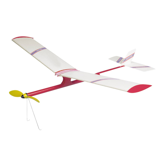
D r a g o n f l y
Technical data:
Wingspan:
800 mm
Length:
650 mm
Wing area:
Tailplane:
2.2 dm2
Complete area:
11.8 dm2
Weight:
80 gm
Wing loading:
6.8 g/dm2
Propellor:
Rubber motor:
1 x 3 x 2500 mm
Pack contents
Fuselage tube, balsa strip, beech dowel, steel wire, Depron, prestamped
balsa parts, propellor, rubber motor, wood glue, deco.strips, rubber bands,
sanding block, glasspaper.
Making time as group project approx. 10 hours
Recommended for children aged 12 and above
E102894#1
1 0 2 . 8 9 4
Please Note
The OPITEC range of projects is not intended as play
toys for young children.They are teaching aids for young
people learning the skills of Craft, Design and Technolo-
gy.These projects should only be undertaken and tested
with the guidance of a fully qualified adult.
The finished projects are not suitable to give to children
under 3 years old. Some parts can be swallowed. Dan-
ger of suffocation!
9.6 dm2
24 x 36cm
©
by B. Elsner
1
Advertisement

Subscribe to Our Youtube Channel
Related Manuals for Opitec Dragonfly 102.894


Summary of Contents for Opitec Dragonfly 102.894
- Page 1 1 0 2 . 8 9 4 D r a g o n f l y Please Note The OPITEC range of projects is not intended as play toys for young children.They are teaching aids for young people learning the skills of Craft, Design and Technolo- gy.These projects should only be undertaken and tested...
-
Page 2: Material Information
1. Product informatiom: Article: Flying model in constuction pack form Flying conditions: Fine weather, little or no wind Use: In Design Technology, Key stage 3 2. Material information 2.1. Material: Balsa wood (Tropical wood, soft and light)) Beech (Deciduous hardwood) Working: Both woods must be sawn and shaped Joining:... -
Page 3: Material List
4. Material List Description Material Quant. Size Part N° 1 / 2 / 3 Fuselage Card ø 19,5/18,3 x 420 mm Rubber motor Rubberband 1 x 3 x 2500 mm 4 / 1 2 Dowel ø 3 x 500 mm Skids Spring steel ø... - Page 4 5. Parts list for the ready made parts Description Quant. Material Size in mm Fuselage Card tube 19 dia x 1 x 400 Nose support Card tube 19 dia x 1 x 10 Tail end support Card tube 19dia x 1 x 10 Rubber band Beech dowel 3 dia x 40 holder...
-
Page 5: Planning Overview
6. Instructions General notes: The glued joints must be allowed to dry thoroughly otherwise they may warp or gradually come apart. Whilst some of the parts are drying other work can be undertaken. Balsa wood and foam sheet can be glued together with white glue. Other glues must be tried on the Styropor / Depron first as any containing a solvent will attack the foam. - Page 6 6.1.7 Glue the leading edge (19) on to the Depron wing (18) hold with pins (insert the pins at an angle) Sk3 6.1.8 Glue the trailing edge (20) in position as in 1.6+1.7. Leave to dry for two hours!!!!! 6.1.9 The wings are marked RF = Right front and LF=left front Sk.
- Page 7 6.1.13 Cut the ribs (21) from the pre-stamped balsa sheet and fix them to the plan with two drops of glue (Sk6) Note: The spots of glue will be removed later. The roundest part of the rib faces forward. 6.1.14 Cut and remove a strip of sellotape from the underside of the wing aprox 5mm left and right of each rib (Sk5), otherwise the glue will not stick at a later stage.
- Page 8 6.1.20 Clean up the outside of the wings (ribs,depron) 6.1.21 The inner end of the wings must be angled. Support one end of the wing with a scrap piece of depron (sk7) and sand the other end as shown (Sk7) Sk.
- Page 9 6.1.27 Cut out the plans (Page 25/27 sk.10) and sellotape them together. Place a drop of glue on the oval points. 6.1.28 Press the pattern on the 410mm long depron sheet. The rear edge of the tailplane should be parallel with the edge of the foam sheet (sk.10)
- Page 10 6.3 Assembling the wing Pylon: 6.3.1 Cut out the plans (page 29/31/33) along the lines and sellotape them together. 6.3.2 Cut out the Pylon parts (7,8/9 =10) from the pre-stamped balsa sheet. Glue them together accurately (sk.12) 6.3.3 Leave them to dry. Mark both parts left and right (in flight direction) Here approx.
- Page 11 6.3.10 Cut a 7mm piece from the ring made in step 3.4. This ring is the rear end support and should be glued into the end of the tube with the slot at the bottom (sk.15). 6.3.11 Chamfer the front end of the fuselage tube lightly so that the propellor will fit. The bearing head must sit ex- actly.
- Page 12 6.3.16 Loosen the fuselage from the board, then turn it over and lay it with the tailplane uppermost. Pin the tube t o the board as shown (sk.18/19) Sk. 18 Block 6.3.17 Glue the Pylons (dowels on inside) as shown to the fuselage and the carrier (6) The bead of glue must run above the line (see sk.19).
- Page 13 6.3.21 Double a ruber band and slide it on to the tube fuselage. Insert the wire skids (5) under the band as shown in Sk.21. Sk. 21 6.3.22 Place the fuselage and skids and on a flat surface. Make sure the tailplane is square and the skids bend backwards Glue the skids in position.
- Page 14 6.4. The rubber motor 6.4.1 Untwist the rubber strands and lay them out on a table top. Tie them together as shown in the diagram. Pull the knot so it is really small and tight. As a security measure apply a little glue to the knot. Sk.
- Page 15 6.5 Balancing the model 6.5.1 Balancing the propellor: Let the propellor spin lightly on its own and note how comes to a rest. Add a drop of glue behind the tip of the propellor blade that is the hightest. Once dry try again until the propellor comes to rest in a different po- sition each time it spins 6.5.2 Place the wings on the Pylons and hold them in position with a diagonally stretched rubber band.
- Page 16 6.6.2 Flying with power: Wind the motor up 200 turns Note: If you use a Drehfix mechanical winder you will only need 100 turns, as it works at a ratio of 1:2! Attatch the Drehfix to the propellor hub and turn If you wind it up by hand, you will need to tension the rubber by holding the rear dowel away from the plane so that the propellor engages.
- Page 17 Pattern for the Right hand wing Scale 1 : 1 Wing outer edge Wing tip strip (23) Wing bending lines Wing tip(22) Sellotape E102894#1...
- Page 18 E102894#1...
- Page 19 Wing pattern for right hand wing Scale 1 : 1 Trailing edge (20) Leading edge (19) with bending lines Centre of gravity Wing inner side E102894#1...
- Page 20 E102894#1...
- Page 21 Wing pattern for the left hand wing Scale 1 : 1 Sellotape Wing tip (22) Wing tip strip (23) Wing bending lines Wing outer edge E102894#1...
- Page 22 E102894#1...
- Page 23 Wing pattern for the left hand wing Scale 1 : 1 Wing inner side centre of gravity Wing bending lines Leading edge(19) Trailing edge (20) E102894#1...
- Page 24 E102894#1...
- Page 25 Pattern for parts 15, 16, 17 and 22 Scale 1 : 1 Bend left or right to correct flight pattern E102894#1...
- Page 26 E102894#1...
- Page 27 Patterns for parts 15, 16, 17 and 22 Scale 1 : 1 E102894#1...
- Page 28 E102894#1...
- Page 29 Fuselage 1 (Scale 1 : 1) approx. 1 mm E102894#1...
- Page 30 E102894#1...
- Page 31 Fuselage 2 (Scale 1 : 1) E102894#1...
- Page 32 E102894#1...
- Page 33 Fuselage 3 (Scale 1 : 1) E102894#1...
- Page 34 E102894#1...
- Page 35 Pattern for bending the wire skids Tail fin 1. Bend the steel wire in the middle as shown 2. Bend as shown in the pattern Tail plane Round base Pylon When bending steps 2,3 and 4 the legs can be Keel held together 3.
Need help?
Do you have a question about the Dragonfly 102.894 and is the answer not in the manual?
Questions and answers