Moxa Technologies MDS-G4000 Series Quick Installation Manual
Hide thumbs
Also See for MDS-G4000 Series:
- Quick installation manual (18 pages) ,
- Quick installation manual (25 pages)

Subscribe to Our Youtube Channel
Related Manuals for Moxa Technologies MDS-G4000 Series


Summary of Contents for Moxa Technologies MDS-G4000 Series
- Page 1 MDS-G4000/MDS-G4000-L3 Series Quick Installation Guide Version 1.2, June 2021 Technical Support Contact Information www.moxa.com/support 2021 Moxa Inc. All rights reserved. P/N: 1802040000004 *1802040000004*...
-
Page 2: Package Checklist
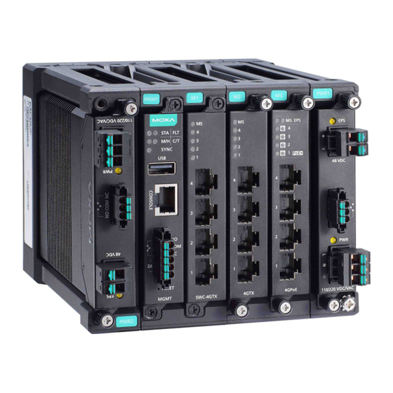
Package Checklist Moxa’s MDS-G4000/MDS-G4000-L3 Series industrial modular DIN-rail switch is shipped with the following items. If any of these items are missing or damaged, please contact your customer service representative for assistance. • 1 MDS-G4000 or MDS-G4000-L3 Series switch • RJ45-to-RS-232 9-pin female console cable •... - Page 3 3. Module status 4. Switch and Control module slot 1 (Embedded) 5. Ethernet module slot 2 6. Ethernet module slot 3 7. Ethernet module slot 4 (For MDS-G4020/28, MDS-G4020/28-L3) 8. Ethernet module slot 5 (For MDS-G4020/28, MDS-G4020/28-L3) 9. External power input status from EPS 10.
-
Page 4: Ethernet Modules
Ethernet Modules (Hardware Rev.2.0.0 and above) NOTE Transceivers for the LM-7000H-4GSFP module are sold separately. Refer to Supported SFP Modules for list of supported transceivers. LM-7000H-4GTX LM-7000H-4GSFP LM-7000H-4GPoE LM-7000H-4TX LM-7000H-4PoE Power Modules (Hardware Rev.2.1.0 and above) NOTE The PWR-LV-P48 power module is certified for Hazardous Location use. - Page 5 MDS-G4020/28 and MDS-G4020/28-L3 Series Insert the upper lip of the DIN rail into the DIN-rail mounting kit. Press the device towards the DIN rail until it snaps into place. Pull down the two latches one by one to release the DIN-rail kit and lift up to remove the device from the DIN rail.
- Page 6 Rack-mounting Dimensions and Instructions (Optional: RK-3U-01) The rack mount kit is designed for two MDS-G4028 or MDS-G4028-L3 products. Assemble the right and left part of the kit (indicated with No. 1 in the diagram) with four screws each. Assemble the part of the rack kit (indicated with No. 2 in the diagram) with eight screws in order to combine two MDS-G4028 or MDS-G4028-L3 products.
-
Page 7: Matters That Require Attention
Rack Mount Front View Rack Mount Rear View Matters That Require Attention 1. Elevated Operating Temperature: If installed in a closed or multi-unit rack assembly, the operating ambient temperature of the rack environment may be greater than room temperature. Therefore, consideration should be given to installing the equipment in an environment compatible with the maximum ambient temperature (Tma) specified by the manufacturer. - Page 8 given to supply connections other than direct connections to the branch circuit (e.g. use of power strips). ATTENTION Safety First! Be sure to disconnect the power cord before installing and/or wiring your Ethernet Switch. Calculate the maximum possible current in each power wire and common wire. Observe all electrical codes dictating the maximum current allowable for each wire size.
-
Page 9: Power Terminal Blocks
ATTENTION For Hazardous Location Use The PoE capacity of the PWR-LV-P48 is only certified for use in hazardous locations up to a maximum power budget of 369.6 W and a maximum output of up to 15.4 W per port. For the PWR-HV-NP, the 110/220 VAC/VDC power supplies provide power to the switch. - Page 10 PoE Power Terminal Blocks Remove 8 to 9 mm of the DC wires’ protective cover. Use a tool to push the spring mechanism inwards to open it. Insert the negative/positive (-/+) DC wires into the terminals. Release the spring mechanism. Insert the terminal block connector prongs into the terminal block receptor.
-
Page 11: Wiring The Relay Contact
Wiring the Relay Contact Each power module has one relay output that can provide two types of relay output. Refer to the table below for detailed information. The relay contact is used to detect user-configured events. Two wires are attached to the relay pins with normally close and normally open options. - Page 12 NOTE When wiring the digital input, we suggest using the cable type - AWG (American Wire Gauge) 16-28 (1.31-0.0804 mm ) and the corresponding pin type cable terminals. The rated temperature of wiring should be at least 105°C. Remove 8 to 9 mm of the DC wires’ protective cover. Use a tool to push the spring mechanism inwards to open it.
- Page 13 Installing and Removing the Power Modules The power supply units are hot-swappable when both power modules are installed. You have the option to mount or remove the power supply units while the device is operating. To install a power module: 1.
-
Page 14: Usb Connection
USB Connection The USB connection is reserved for functions that may be required in the future. Description VCC (+5V) D- (Data-) D+ (Data+) GND (Ground) The Reset Button (Diameter 0.9 mm) The reset button can perform two functions. One is to reset the switch to factory default settings and the other is to reboot the switch if the button has been depressed and release immediately. -
Page 15: Led Indicators
LED Indicators The function of each LED is described in the table below. Color State Description System LEDs Normal operation. Green Blinking 1. The system is booting up. (STATE) The system failed to initialize. 1. Switch failed to initialize. 2. EEPROM information error. When the switch boots up and the (FAULT) Blinking... - Page 16 SWC-4GTX Color State Description Normal operation. Green Blinking This module is booting up. The module is out of service. (Module 1. The module failed to initialize. State) 2. A module designed for a different model was inserted. When the port is active and links on 1,000 Mbps.
- Page 17 LM-7000H-4GTX/LM-7000H-4GSFP/LM-7000H-4TX Color State Description Normal operation. Green Blinking This module is booting up. The module is out of service. (Module 1. The module failed to initialize. State) 2. A module designed for a different model was inserted. When the port is active and links on at 100 Mbps.
- Page 18 LM-7000H-4GPoE/LM-7000H-4PoE Color State Description Normal operation. Green Blinking The module is booting up. This module is out of service. 1. The module failed to initialize. 2. A user inserted a module designed (Module State) for a different model. 3. When performing a cold start, the module was removed and inserted before initialization was complete.
-
Page 19: Specifications
PWR-HV-P48/PWR-LV-P48 Color State Description External power is being supplied to EPS (External the module's EPS input. Amber Power Supply) No external power supply for PoE. Power is being supplied to the module's power input. Amber Power is not being supplied to the module's power input. - Page 20 When using PWR-HV-P48: Power Consumption 110 VDC: 12.43 W (without modules 220 VDC: 12.87 W consumption) 110 VAC: 13.42 W 220 VAC: 14.08 W When using PWR-LV-P48: 24 VDC: 12.67 W 48 VDC: 13.2 W Power LM-7000H-4GTX: 3.63 W Consumption of LM-7000H-4GPoE: 3.8 W module LM-7000H-4GSFP: 4.8 W...
- Page 21 Weight MDS-G4012/MDS-G4012-L3 Series: 2.00 kg (4.41 lb) MDS-G4020/MDS-G4020-L3 Series: 2.50 kg (5.51 lb) MDS-G4028/MDS-G4028-L3 Series: 2.84 kg (6.26 lb) LM-7000H-4GSFP: 0.3 kg (0.66 lb) LM-7000H-4GTX: 0.24 kg (0.53 lb) LM-7000H-4GPoE: 0.31 kg (0.69 lb) LM-7000H-4TX: 0.24 kg (0.53 lb) LM-7000H-4PoE: 0.31 kg (0.69 lb) PWR-HV-P48/PWR-LV-P48: 0.36 kg (0.69 lb) PWR-HV-NP/PWR-LV-NP: 0.34 kg (0.75 lb) Installation...
-
Page 22: Supported Sfp Modules
Details See www.moxa.com/warranty Supported SFP Modules Module Description SFP-1FEMLC-T SFP module with 1 100Base multi-mode, LC connector for 2/4 km transmission, -40 to 85°C operating temperature SFP-1FESLC-T SFP module with 1 100Base single-mode with LC connector for 40 km transmission, -40 to 85°C operating temperature SFP-1FELLC-T SFP module with 1 100Base single-mode with LC... - Page 23 SFP-1G40BLC WDM-type (BiDi) SFP module with 1 1000BaseSFP port with LC connector for 40 km transmission; TX 1550 nm, RX 1310 nm, 0 to 60°C operating temperature SFP-1G40BLC-T WDM-type (BiDi) SFP module with 1 1000BaseSFP port with LC connector for 40 km transmission; TX 1550 nm, RX 1310 nm, -40 to 85°C operating temperature SFP-1GSXLC...
-
Page 24: Restricted Access Locations
Restricted Access Locations This equipment is intended to be used in Restricted Access Locations, such as a computer room, with access limited to service personnel or users who have been instructed on how to handle the metal chassis of equipment that is very hot. The location should only be accessible with a key or through a security system. - Page 25 Conductors ≧105°C suitable for rated cable temperature Hazardous EN 60079-0:2012+A11:2013, EN 60079-15:2010 Location Class I, Division 2, Groups A, B, C, and D Address of No. 1111, Heping Rd., Bade Dist., Taoyuan City manufacturer 334004, Taiwan CID2 Temp. Code ATEX 165°C (T3) Temp.
Need help?
Do you have a question about the MDS-G4000 Series and is the answer not in the manual?
Questions and answers