Moxa Technologies MDS-G4000 Series Quick Installation Manual
Hide thumbs
Also See for MDS-G4000 Series:
- Quick installation manual (26 pages) ,
- Quick installation manual (25 pages)
Table of Contents
Advertisement
Quick Links
Quick Installation Guide
Moxa Americas:
Toll-free: 1-888-669-2872
Tel:
1-714-528-6777
Fax:
1-714-528-6778
Moxa Europe:
Tel:
+49-89-3 70 03 99-0
Fax:
+49-89-3 70 03 99-99
Moxa India:
Tel:
+91-80-4172-9088
Fax:
+91-80-4132-1045
MDS-G4000 Series
Version 1.1, April 2020
Technical Support Contact Information
www.moxa.com/support
2020 Moxa Inc. All rights reserved.
Moxa China (Shanghai office):
Toll-free: 800-820-5036
Tel:
+86-21-5258-9955
Fax:
+86-21-5258-5505
Moxa Asia-Pacific:
Tel:
+886-2-8919-1230
Fax:
+886-2-8919-1231
P/N: 1802040000002
*1802040000002*
Advertisement
Table of Contents

Subscribe to Our Youtube Channel
Related Manuals for Moxa Technologies MDS-G4000 Series


Summary of Contents for Moxa Technologies MDS-G4000 Series
- Page 1 MDS-G4000 Series Quick Installation Guide Version 1.1, April 2020 Technical Support Contact Information www.moxa.com/support Moxa Americas: Moxa China (Shanghai office): Toll-free: 1-888-669-2872 Toll-free: 800-820-5036 Tel: 1-714-528-6777 Tel: +86-21-5258-9955 Fax: 1-714-528-6778 Fax: +86-21-5258-5505 Moxa Europe: Moxa Asia-Pacific: Tel: +49-89-3 70 03 99-0...
-
Page 2: Package Checklist
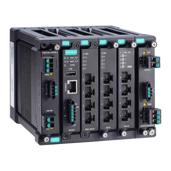
Package Checklist Moxa’s MDS-G4000 Series industrial modular DIN-rail switch is shipped with the following items. If any of these items are missing or damaged, please contact your customer service representative for assistance. • 1 MDS-G4000 switch • RJ45 to RS-232 9 pin female console cable •... - Page 3 9. External power input status from EPS 10. Ethernet module slot 6 (For MDS-G4028) 11. Ethernet module slot 7 (For MDS-G4028) 12. External Power Supply input for PoE 13. Redundant power module slot 1 14. Redundant power module slot 2 15.
- Page 4 LM-7000H-4GPoE LM-7000H-4TX LM-7000H-4PoE Power Modules (Hardware Rev.2.1.0 and above) PWR-HV-P48 PWR-LV-P48 DIN-Rail Dimension and Instructions MDS-G4012 Series MDS-G4020/MDS-G4028 Series 1. Insert the upper lip of the DIN-rail into the DIN-rail mounting kit. 2. Press the device towards the DIN-rail until it snaps into place. 3.
- Page 5 3.5 to 4 mm, as shown in the figure shown on the right. Use the MDS-G4000 Series with the wall mounting kit attached, as a guide to mark the correct locations of the eight screws.
-
Page 6: Matters That Require Attention
Rack Mount Top View Rack Mount Front View Rack Mount Rear View Matters That Require Attention 1. Elevated Operating Temperature: If installed in a closed or multi-unit rack assembly, the operating ambient temperature of the rack environment may be greater than room temperature. Therefore, consideration should be given to installing the equipment in an environment compatible with the maximum ambient temperature (Tma) specified by the manufacturer. - Page 7 Connecting the Power Inputs The MDS-G4000 Series supports 2 types of power supply: • PWR-HV-P48: one 110/220 VAC/VDC (90 to 264 VAC, 88 to 300 VDC), one 48VDC PoE power input for PoE+ ports.
-
Page 8: Power Terminal Blocks
Power Terminal Blocks The connection for power input and PoE external power supply is on the power modules. PWR-HV-P48 STEP 1: Insert the neutral/line (L/N/Ground) AC wires into the terminals. STEP 2: Insert the terminal block connector into the terminal block receptor. -
Page 9: Wiring The Relay Contact
5 pound-inches. The rated temperature of wiring should be at least 105°C. NOTE When two power units are installed on the MDS-G4000 Series switch, both power units will be activated simultaneously, which will enable power redundancy. - Page 10 Install/Remove the Ethernet module The Ethernet modules are hot-swappable for the same module type. You have the option to mount or remove the Ethernet module while the device is operating. NOTE 1. When performing a cold start, you cannot remove and insert a module before booting up as it will cause the module to initially fail.
-
Page 11: Usb Connection
Grounding the Moxa Industrial DIN-rail Switch Grounding and wire routing help limit the effects of noise due to electromagnetic interference (EMI). Run the ground connection from the ground screw to the grounding surface prior to connecting devices. NOTE Using a shielded cable achieves better electromagnetic resistance. -
Page 12: Led Indicators
LED Indicators The function of each LED is described in the table below. Color State Description System LEDs Normal operation 1. The system is booting up 2. When pressing the reset button Green Blinking and continue 5 seconds to reset (STATE) factory default The system has initially failed... - Page 13 LM-7000H-4GTX/LM-7000H-4GSFP/LM-7000H-4TX Color State Description Normal operation Green Blinking This module is booting up The module is out of service (Module 1. The module has initially failed State) 2. When insert module by different model When the port is active and links on 100 Mbps.
- Page 14 LM-7000H-4GPoE/LM-7000H-4PoE Color State Description Normal operation Green Blinking The module is booting up This module is out of service. 1. The module has initially failed (Module State) 2. When insert module by different model 3. When cold start, remove and insert module before initial done Normal operation (External Power...
-
Page 15: Specifications
Color State Description When detecting over current or short Blinking circuit on the powered Device (PD) PoE is normal operation PWR-HV-P48/PWR-LV-P48 Color State Description External Power Supply is being EPS (External supplied to the module's EPS input Amber Power Supply) No external power supply for PoE Power is being supplied to the module's power input... - Page 16 Input Current When using PWR-HV-P48: (without modules 110 VDC: 0.11 A consumption) 220 VDC: 0.06 A 110 VAC: 0.29 A 220 VAC: 0.18 A When using PWR-LV-P48: 24 VDC: 0.53 A 48 VDC: 0.28 A PWR-HV-P48: Peak Inrush Current 110 VAC: <10 A (t > 0.1 ms) 220 VAC: <20 A (t >...
-
Page 17: Restricted Access Locations
CISPR 32, FCC Part 15B Class A IEC 61000-4-2 ESD: Contact: 8 kV; Air: 15 kV IEC 61000-4-3 RS: 80MHz to 1GHz: 20 V/m IEC 61000-4-4 EFT: Power: 4 kV; Signal: 4 kV IEC 61000-4-5 Surge: Power 4 kV; Signal: 4 kV IEC 61000-4-6 CS: 10V IEC 61000-4-8 PFMF IEC 61000-4-11 Voltage Dips &...
Need help?
Do you have a question about the MDS-G4000 Series and is the answer not in the manual?
Questions and answers