Moxa Technologies PT-7728 User Manual
Hide thumbs
Also See for PT-7728:
- User manual (87 pages) ,
- Hardware installation manual (9 pages) ,
- Manual (84 pages)

Subscribe to Our Youtube Channel
Related Manuals for Moxa Technologies PT-7728


Summary of Contents for Moxa Technologies PT-7728
- Page 1 Moxa PowerTrans Switch PT-7728 User’s Manual www.moxa.com/product Third Edition, February 2009 © 2009 Moxa Inc. All rights reserved. Reproduction without permission is prohibited.
-
Page 2: Copyright Notice
Information in this document is subject to change without notice and does not represent a commitment on the part of Moxa. Moxa provides this document “as is,” without warranty of any kind, either expressed or implied, including, but not limited to, its particular purpose. Moxa reserves the right to make improvements and/or changes to this manual, or to the products and/or the programs described in this manual, at any time. -
Page 3: Table Of Contents
Table of Contents Chapter 1 Introduction ....................1-1 Overview ..........................1-2 Package Checklist ......................... 1-2 Software Features ......................... 1-2 Chapter 2 Getting Started ..................2-1 Serial Console Configuration (115200, None, 8, 1, VT100) ..........2-2 ... - Page 4 The Virtual LAN (VLAN) Concept ................ 3-45 Sample Applications of VLANs using PT-7728 ............. 3-48 Configuring Virtual LAN ..................3-49 Using Multicast Filtering ....................3-51 The Concept of Multicast Filtering ................. 3-51 Configuring IGMP Snooping .................. 3-54 ...
-
Page 5: Chapter 1 Introduction
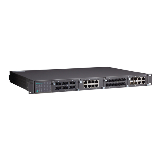
Introduction Chapter 1 Welcome to the PowerTrans PT-7728, a managed redundant Gigabit Ethernet switch designed especially for connecting Ethernet-enabled devices for industrial field applications. The following topics are covered in this chapter: Overview Package Checklist Software Features... -
Page 6: Overview
You can install up to 4 Gigabit Ethernet ports and 24 Fast Ethernet ports. Optional front or rear wiring makes the PT-7728 suitable for different applications. Package Checklist The PowerTrans PT-7728 is shipped with the following items. If any of these items is missing or damaged, please contact your customer service representative for assistance. 1 PowerTrans PT-7728 Hardware installation guide CD-ROM with user’s manual and SNMP MIB file... -
Page 7: Chapter 2 Getting Started
PT-7728’s IP address, you can open the serial console by connecting the PT-7728 to a PC’s COM port with a short serial cable. You can open the Telnet or web console over an Ethernet LAN or over the Internet. -
Page 8: Serial Console Configuration (115200, None, 8, 1, Vt100)
Moxa website. Before running PComm Terminal Emulator, use an RJ45 to DB9-F (or RJ45 to DB25-F) cable to connect the PT-7728’s console port to your PC’s COM port (generally COM1 or COM2, depending on how your system is set up). - Page 9 115200 for Baud Rate, 8 for Data Bits, None for Parity, and 1 for Stop Bits. 4. On the Terminal tab, select VT100 for Terminal Type. Click OK. 5. In the terminal window, the PT-7728 will prompt you to select a terminal type. Enter 1 to select ansi/vt100 and press Enter.
- Page 10 Password field blank and press Enter. 7. The Main Menu of the PT-7728’s serial console should appear. (In PComm Terminal Emulator, you can adjust the font by selecting Font… in the Edit menu.) 8.
-
Page 11: Configuration By Telnet Console
Configuration by Telnet Console You may open the PT-7728’s Telnet or web console over a network. This requires that the PC host and PT-7728 are on the same logical subnet. You may need to adjust your PC host’s IP address and subnet mask. - Page 12 In the terminal window, select Preferences… from the Terminal menu on the menu bar. The Terminal Preferences window should appear. Make sure that VT100 Arrows is checked. Use the following keys on your keyboard to navigate the PT-7728’s Telnet console: Function Up, down, right, left arrow keys...
-
Page 13: Configuration By Web Browser
To connect to the PT-7728’s Telnet or web console, your PC host and the PT-7728 must be on the same logical subnet. NOTE If the PT-7728 is configured for other VLAN settings, you must make sure your PC host is on the management VLAN. NOTE When connecting to the PT-7728’s Telnet or web console, first connect one of PT-7728’s... -
Page 14: Disabling Telnet And Browser Access
Disabling Telnet and Browser Access If you are connecting the PT-7728 to a public network but do not intend to manage it over the network, we suggest disabling both the Telnet and web consoles. This is done through the serial console, by navigating to System Identification under Basic Settings. -
Page 15: Chapter 3 Featured Functions
These functions can be accessed by serial, Telnet, or web console. The serial console can be used if you do not know PT-7728’s IP address and requires that you connect the PT-7728 to a PC COM port. The Telnet and web consoles can be opened over an Ethernet LAN or the Internet. -
Page 16: Configuring Basic Settings
PT-7728 User’s Manual Featured Functions Configuring Basic Settings Basic Settings includes the most common settings required by administrators to maintain and control the PT-7728. System Identification System Identification items are displayed at the top of the web console and will be included in alarm emails. -
Page 17: Password
ATTENTION By default, no password is assigned to the PT-7728’s web, Telnet, and serial consoles. If a password is assigned, you will be required to enter the password when you open the serial console, Telnet console, or Web console. -
Page 18: Accessible Ip
The PT-7728 uses an IP address-based filtering method to control access. You may add or remove IP addresses to limit access to the PT-7728. When the accessible IP list is enabled, only addresses on the list will be allowed access to the PT-7728. Each IP address and... -
Page 19: Port
10M-Full 10M-Half FDX Flow Ctrl This setting enables or disables flow control for the port when the port's Speed is set to Auto. The final result will be determined by the Auto process between the PT-7728 and connected devices. -
Page 20: Network
The Network configuration allows users to configure both IPv4 and IPv6 parameters for management access over the network. This Moxa Ethernet switch supports both IPv4 and IPv6, and can be managed through either of these address types. An explanation of each configuration item follows. -
Page 21: Ipv4
IPv4 Auto IP Configuration Setting Description Factory Default Disable Select this to set the PT-7728’s IP address manually. By DHCP The PT-7728’s IP address will be assigned automatically by the network’s DHCP server. Disable By BootP The PT-7728’s IP address will be assigned automatically by the network’s BootP server. - Page 22 PT-7728 User’s Manual Featured Functions Global Unicast Address Setting Description Factory Default None Display an IPv6 Global Unicast address. The network portion of a Global Unicast address can be configured by specifying the Global Unicast Prefix and using a EUI-64 interface ID in the low order 64 bits.
-
Page 23: Time
NOTE The PT-7728 has a built-in real time clock. Users do not need to update the Current Time and Current Date to set the initial time for the PT-7728 after each reboot. This is especially useful when the network does not have an Internet connection to an NTP server, or there is no NTP server on the LAN. - Page 24 This specifies the number of hours that the time None should be offset forward during Daylight Savings Time. System Up Time This indicates how long the PT-7728 remained up since the last cold start. The up time is indicated in seconds. Time Zone Setting Description...
-
Page 25: Configuring Ieee 1588/Ptp
SNTP is able to provide synchronization accuracy within about 1 ms. However, this is not precise enough for raw data sampled values. Moxa’s PT-7728-PTP IEC 61850-3 fast Ethernet switches support the latest version of IEEE 1588 v2 technology to fulfill precise time synchronization requirements for protection and control applications. -
Page 26: Ptp Setting
PT-7728 User’s Manual Featured Functions PTP Setting Operation IEEE 1588/PTP Setting Description Factory Default Operation Disable or enable IEEE 1588(PTP) operation Disabled Configuration IEEE 1588/PTP Setting Description Factory Default Clock Mode Supports software-based IEEE 1588(PTP) mode Disabled Sync Interval Period for sending synchronization messages (in... -
Page 27: System File Update-By Remote Tftp
PTP_DISABLED System File Update—By Remote TFTP The PT-7728 supports saving your configuration or log file to a remote TFTP server or local host. Other PT-7728 switches can also load the configuration at a later time. The PT-7728 also supports loading firmware or configuration files from the TFTP server or a local host. -
Page 28: System File Update-By Local Import/Export
Export button to save the file. Upgrade Firmware To import a new firmware file onto the PT-7728, click Browse to select the firmware file that is saved on your computer. The upgrade procedure will proceed automatically after clicking Import. -
Page 29: Factory Default
Port trunking can be used to combine up to 8 ports between two PT-7728 switches. If all ports on both switch units are configured as 100BaseTX and they are operating in full duplex, the potential bandwidth of the connection will be 1600 Mbps. -
Page 30: Configuring Port Trunking
Trk1, Trk2, Trk3, Trk4 This specifies the current trunk group. Trk1 Trunk Type Setting Description Factory Default Static This selects Moxa's proprietary trunking protocol. Static This selects LACP (IEEE 802.3ad, Link Static LACP Aggregation Control Protocol). Available Ports/Member Ports Setting... -
Page 31: Configuring Snmp
Configuring SNMP The PT-7728 supports SNMP V1, V2c, and V3. SNMP V1 and SNMP V2c use a community string match for authentication, which means that SNMP servers access all objects with read-only or read/write permissions using the community strings public and private by default. SNMP V3 requires that you select an authentication level of MD5 or SHA, and is the most secure protocol. -
Page 32: Snmp Read/Write Settings
PT-7728 User’s Manual Featured Functions This uses an account with admin No-Auth or user to access objects This provides authentication based Authentication on HMAC-MD5, or HMAC-SHA MD5 or SHA based on MD5 algorithms. 8-character passwords or SHA are the minimum requirement for authentication. - Page 33 For SNMP V3, there are two levels of privilege for different accounts to access the PT-7728. Admin privilege provides access and authorization to read and write the MIB file. User privilege allows reading of the MIB file only.
-
Page 34: Trap Settings
PT-7728 User’s Manual Featured Functions Authentication will be based on the HMAC-MD5 algorithms. 8-character MD5-Auth passwords are the minimum requirement for authentication. Authentication will be based on the HMAC-SHA algorithms. 8-character SHA-Auth passwords are the minimum requirement for authentication. User Data Encryption Key (for SNMP V1, V2c, V3 and V3 only) -
Page 35: Snmp Inform Mode
This is a particularly important feature for industrial applications, since it could take several minutes to locate the disconnected or severed cable. For example, if the PT-7728 is used as a key communications component of a production line, several minutes of downtime can result in a big loss in production and revenue. -
Page 36: The Turbo Ring Concept
NOTE Most managed switches by Moxa support two proprietary Turbo Ring protocols: Turbo Ring refers to the original version of Moxa’s proprietary redundant ring protocol, which has a recovery time of under 300 ms. Turbo Ring V2 refers to the new generation Turbo Ring, which has a recovery time of under 20 ms. - Page 37 PT-7728 User’s Manual Featured Functions Turbo Ring with even number of switches If the number of Ethernet switches in the Turbo Master Ring is 2N (an even number), the backup segment is one of the two segments connected to the (N+1)st switch (i.e., the unit directly opposite the master).
- Page 38 PT-7728 User’s Manual Featured Functions Ring Coupling Configuration For some systems, it may not be convenient to connect all devices in the system in a single redundant ring, since some devices could be located in a remote area. For these systems, Ring Coupling can be used to group devices into smaller redundant rings that communicate with each other.
-
Page 39: Configuring Turbo Ring, Turbo Ring V2, And Turbo Chain
PT-7728 User’s Manual Featured Functions Note that the ring coupling settings for a Turbo Ring V2 are different from a Turbo Ring. For Turbo Ring V2, ring coupling is enabled by configuring the Coupling Port (Primary) on Switch B and the Coupling Port (Backup) on Switch A only. You do not need to set up a coupling control port, so Turbo Ring V2 does not require a coupling control line. -
Page 40: Configuring Turbo Ring
This shows which communication protocol is in use: Turbo Ring, Turbo Ring V2, Turbo Chain, RSTP, or none. Master/Slave This indicates whether or not the PT-7728 is the master of the Turbo Ring. This field appears only for Turbo Ring or Turbo Ring V2. NOTE The user does not need to assign the master to use Turbo Ring or Turbo Ring V2. - Page 41 Redundant Ports Description Setting Factory Default This specifies which port on the PT-7728 will be 1st Port Port 1-1 used as the first redundant port. This specifies which port on the PT-7728 will be 2nd Port Port 1-12 used as the second redundant port.
- Page 42 This shows Healthy if the ring is operating normally, and shows Break if the ring’s backup link is active. Ring 1/2—Master/Slave This indicates whether or not the PT-7728 is the master of the Turbo Ring. This field appears only when selected to operate in Turbo Ring or Turbo Ring V2 mode. 3-28...
- Page 43 *Both Ring 1 and Ring 2 must be enabled when using the dual-ring architecture. Set as Master Setting Description Factory Default The PT-7728 is manually selected as the Enabled master. Not checked The Turbo Ring or Turbo Ring V2 protocol Disabled will automatically select the master.
- Page 44 Port 1-1 (without Gigabit Ethernet module) This specifies which port on the Port 1-1 (with Gigabit Ethernet module) 1st Port PT-7728 will be used as the first Ring 2: redundant port. Port 1-3 (without Gigabit Ethernet module) Port 4-1 (with Gigabit Ethernet module)
-
Page 45: The Turbo Chain Concept
Featured Functions The Turbo Chain Concept Moxa’s Turbo Chain is an advanced software technology that gives network administrators the flexibility to construct any type of redundant network topology. When using a Turbo Chain, you first connect the Ethernet switches in a chain and then simply link the two ends of the chain to an Ethernet network, as illustrated in the following figure. -
Page 46: Explanation Of "Current Status" Items
PT-7728 User’s Manual Featured Functions Member Switch Configuration Tail Switch Configuration Explanation of “Current Status” Items Now Active Shows which communication protocol is in use: Turbo Ring, Turbo Ring V2, Turbo Chain, RSTP, or none. The “Ports Status” indicators show Forwarding for normal transmission, Blocked if this port is connected to the Tail port as a backup path and the path is blocked, and Link down if there is no connection. -
Page 47: The Stp/Rstp Concept
Networks that have a complicated architecture are prone to broadcast storms caused by unintended loops in the network. The PT-7728’s STP feature is disabled by default. To be completely effective, you must enable RSTP/STP on every PT-7728 connected to your network. -
Page 48: What Is Stp
It defaults to sending 802.1D style BPDUs if packets with this format are received. STP (802.1D) and RSTP (802.1w) can operate on different ports of the same PT-7728. This feature is particularly helpful when PT-7728 ports connect to older equipment, such as legacy switches. -
Page 49: How Stp Works
PT-7728 User’s Manual Featured Functions What happens if a link failure is detected? As shown in next figure, the STP process reconfigures the network so that traffic from LAN segment 2 flows through Bridge B. STP will determine which path between each bridged segment is most efficient, and then assign a specific reference point on the network. - Page 50 PT-7728 User’s Manual Featured Functions Each bridge must have a Bridge Identifier that specifies which bridge acts as the central reference point, or Root Bridge, for the STP system. Bridges with a lower Bridge Identifier are more likely to be designated as the Root Bridge. The Bridge Identifier is calculated using the MAC address of the bridge and a priority defined for the bridge.
-
Page 51: Stp Example
PT-7728 User’s Manual Featured Functions a link without waiting to ensure that all other bridges in the network have had time to react to the change. The main benefit of RSTP is that the configuration decision is made locally rather than network-wide, allowing RSTP can carry out automatic configuration and restore a link faster than STP. -
Page 52: Configuring Stp/Rstp
PT-7728 User’s Manual Featured Functions Using STP on a Network with Multiple VLANs IEEE Std 802.1D, 1998 Edition, does not take into account VLANs when calculating STP information—the calculations only depend on the physical connections. Consequently, some network configurations will result in VLANs being subdivided into a number of isolated sections by the STP system. - Page 53 This field shows which communication protocol is being used—Turbo Ring, RSTP, or neither. Root/Not Root This field appears only for RSTP mode. It indicates whether or not this PT-7728 is the Root of the Spanning Tree (the root is determined automatically).
- Page 54 ≦ ≦ The PT-7728’s firmware will alert you immediately if any of these restrictions are violated. For example, suppose Hello Time = 5 sec, Max. Age = 20 sec, and Forwarding Delay = 4 sec. This does not violate Eqs. 1 through 3, but it violates Eq. 4: 2 * (Hello Time + 1 sec) = 12 sec, and 2 * (Forwarding Delay –...
-
Page 55: Using Traffic Prioritization
Quality of Service for your network. The rules define different types of traffic and specify how each type should be treated as it passes through the switch. The PT-7728 can inspect both IEEE 802.1p/1Q layer 2 CoS tags, and even layer 3 TOS information to provide consistent classification of the entire network. - Page 56 3 TOS enabled prioritization scheme. Traffic Prioritization The PT-7728 classifies traffic based on layer 2 of the OSI 7 layer model, and the switch prioritizes received traffic according to the priority information defined in the received packet. Incoming traffic is classified based upon the IEEE 802.1D frame and is assigned to the appropriate priority...
-
Page 57: Configuring Traffic Prioritization
PT-7728 User’s Manual Featured Functions The PT-7728 will check a packet received at the ingress port for IEEE 802.1D traffic classification, and then prioritize it based upon the IEEE 802.1p value (service levels) in that tag. It is this 802.1p value that determines which traffic queue the packet is mapped to. -
Page 58: Cos Mapping
Inspect TOS Setting Description Factory Default Enable/Disable This enables or disables the PT-7728 to inspect the Type Enable of Service (TOS) bits in IPV4 frame to determine the priority of each frame. Inspect COS Setting Description... -
Page 59: Using Virtual Lan
49 to 64: High Using Virtual LAN Setting up Virtual LANs (VLANs) on your PT-7728 increases the efficiency of your network by dividing the LAN into logical segments, as opposed to physical segments. In general, VLANs are easier to manage. -
Page 60: Benefits Of Vlans
In a single VLAN defined on the PT-7728 In several VLANs simultaneously using 802.1Q tagging The standard requires that you define the 802.1Q VLAN ID about each VLAN on your PT-7728 before the switch can use it to forward traffic: Managing a VLAN A new or initialized PT-7728 contains a single VLAN—the Default VLAN. -
Page 61: Communication Between Vlans
VLANs: Tagged and Untagged Membership The PT-7728 supports 802.1Q VLAN tagging, a system that allows traffic for multiple VLANs to be carried on a single physical (backbone, trunk) link. When setting up VLANs you need to understand when to use untagged and tagged membership of VLANs. Simply put, if a port is on a single VLAN it can be an untagged member, but if the port needs to be a member of multiple VLANs, tagged membership must be defined. -
Page 62: Sample Applications Of Vlans Using Pt-7728
PT-7728 User’s Manual Featured Functions Sample Applications of VLANs using PT-7728 In this application, Port 1 connects a single untagged device and assigns it to VLAN 5; it should be configured as Access Port with PVID 5. Port 2 connects a LAN with two untagged devices belonging to VLAN 2. One tagged device with VID 3 and one tagged device with VID 4. -
Page 63: Configuring Virtual Lan
VLAN and pass it to port 2, but will not remove tags received successfully by Device E. Configuring Virtual LAN VLAN Settings To configure 802.1Q VLAN on the PT-7728, use the VLAN Setting page to configure the ports. VLAN Mode Setting Description Factory Default 802.1Q VLAN... - Page 64 Use the VLAN settings page to configure the PT-7728’s VLAN Unaware mode For certain Power Substation scenarios, some applications may require priority-tagged frames to be received by IEDs. To fulfill these requirements Moxa PT-7728 Series Ethernet switches allow VLAN Unaware Mode operation.
-
Page 65: Using Multicast Filtering
PT-7728 User’s Manual Featured Functions VLAN Table In 802.1Q VLAN table, you can review the VLAN groups that were created, Joined Access Ports, and Trunk Ports, and in Port-based VLAN table, you can review the VLAN group and Joined port. -
Page 66: Multicast Filtering
PT-7728 User’s Manual Featured Functions all end-stations would cause a substantial reduction in network performance. Furthermore, several industrial automation protocols, such as Allen-Bradley, EtherNet/IP, Siemens Profibus, and Foundation Fieldbus HSE (High Speed Ethernet), use multicast. These industrial Ethernet protocols use publisher/subscriber communications models by multicasting packets that could flood a network with heavy traffic. -
Page 67: Igmp Multicast Filtering
Query Mode Query mode allows the PT-7728 to work as the Querier if it has the lowest IP address on the subnetwork to which it belongs. IGMP querying is enabled by default on the PT-7728 to help prevent interoperability issues with some multicast routers that may not follow the lowest IP address election method. -
Page 68: Configuring Igmp Snooping
Static Multicast MAC Some devices may only support multicast packets, but not support either IGMP Snooping or GMRP. The PT-7728 supports adding multicast groups manually to enable multicast filtering. Enabling Multicast Filtering Use the serial console or Web interface to enable or disable IGMP Snooping and IGMP querying. -
Page 69: Add Static Multicast Mac
VLAN. Snooping Enabled Globally Querier Setting Description Factory Default Enable/Disable This enables or disables the PT-7728’s querier function. Enabled if IGMP Snooping is Enabled Globally Static Multicast Router Port Setting Description Factory Default Select/Deselect This selects the ports that will connect to the multicast Disabled routers. -
Page 70: Configuring Gmrp
This enables or disables the GMRP function for the port Disable listed in the Port column GMRP Table The PT-7728 displays the current active GMRP groups that were detected Setting Description Fixed Ports This multicast address is defined by static multicast. -
Page 71: Using Bandwidth Management
For example, so-called “broadcast storms” could be caused by an incorrectly configured topology, or a malfunctioning device. The PT-7728 not only prevents broadcast storms, but can also be configured to a different ingress rate for all packets, giving administrators full control of their limited bandwidth to prevent undesirable effects caused by unpredictable faults. -
Page 72: Using Port Access Control
IEEE 802.1X. Static Port Lock The PT-7728 can also be configured to protect static MAC addresses for a specific port. With the Port Lock function, these locked ports will not learn any additional addresses, but only allow traffic from preset static MAC addresses, helping to block hackers and careless usage. -
Page 73: Configuring Ieee 802.1X
The UDP port of the RADIUS server 1812 Shared Key Setting Description Factory Default alphanumeric A key to be shared between the external RADIUS server None (Max. 40 and PT-7728. Both ends must be configured to use the characters) same key. 3-59... - Page 74 IEEE 802.1X for one or more ports. All end stations must enter usernames and passwords before access to these ports is allowed. 802.1X Re-Authentication The PT-7728 can force connected devices to be re-authorized manually. 802.1X Re-Authentication Setting Description Factory Default Enable/Disable This enables or disables 802.1X Re-Authentication...
-
Page 75: Using Ip Filter
PT-7728 User’s Manual Featured Functions Local User Database Setup Setting Description Factory Default User Name User Name for Local User Database None (Max. 30 characters) Password Password for Local User Database None (Max. 16 characters) Description Description for Local User Database None (Max. -
Page 76: Using Auto Warning
Email Alarm Events setting subsection). 2. Configuring Email Settings To configure PT-7728’s email setup from the serial, Telnet, or web console, enter your Mail Server IP/Name (IP address or name), Account Name, Account Password, Retype New Password, and the email address to which warning messages will be sent. - Page 77 Warning e-mail messages will have sender given in the form: Moxa_PowerTrans_Switch_0001@Switch_Location where Moxa_PowerTrans_Switch is the default Switch Name, 0001 is PT-7728’s serial number, and Switch_Location is the default Server Location. Refer to the Basic Settings section to see how to modify Switch Name and Switch Location.
-
Page 78: Email Setup
PT-7728 User’s Manual Featured Functions Email Setup Mail Server IP/Name Setting Description Factory Default IP address The IP Address of your email server. None Account Name Setting Description Factory Default Max. 45 Charters Your email account. None Password Setting Setting... -
Page 79: Configuring Relay Warning
Events are related to the overall function of the switch, whereas Port Events are related to the activity of a specific port. The PT-7728 supports two relay outputs. You can configure which relay output is related to which events. This helps administrators identify the importance of the different events. -
Page 80: Warning List
Use this table to see if any relay alarms have been issued. Using Line-Swap-Fast-Recovery The Line-Swap Fast Recovery function, which is enabled by default, allows PT-7728 to return to normal operation extremely quickly after devices are unplugged and then re-plugged into different ports. -
Page 81: Using Set Device Ip
DHCP Client or RARP protocol. In effect, PT-7728 acts as a DHCP server by assigning a connected device with a specific IP address stored in its internal memory. Each time the connected device is switched on or rebooted, PT-7728 sends the device the desired IP address. -
Page 82: Configuring Set Device Ip
PT-7728 User’s Manual Featured Functions Configuring Set Device IP Desired IP Address Setting Description Factory Default IP Address Set the desired IP of connected devices. None Configuring DHCP Relay Agent The DHCP Relay Agent makes it possible for DHCP broadcast messages to be sent over routers. - Page 83 PT-7728 User’s Manual Featured Functions 1. The IP address of the relay agent. 2. The MAC address of the relay agent. 3. The combination of IP address and MAC address of the relay agent. 4. A user-defined string. Server IP Address...
-
Page 84: Using Diagnosis
Value field. Users cannot modify it. DHCP Function Table Enable Setting Description Factory Default Enable or Disable Enable or disable DHCP Option 82 function for this Disable port. Using Diagnosis The PT-7728 provides two important tools for administrators to diagnose network systems. Mirror Port 3-70... -
Page 85: Ping
The function’s most unique feature is that even though the ping command is entered from the user’s PC keyboard, the actual ping command originates from PT-7728 itself. In this way, the user can essentially sit on top of PT-7728 and send ping commands out through its ports. -
Page 86: Lldp
It allows each networking device, such as a Moxa managed switch, to periodically inform its neighbors about its self-information and configurations. As a result, all such devices will have information about their neighbors, and by using SNMP, this knowledge can be transferred to Moxa’s MXview for auto-topology and... -
Page 87: Using Monitor
Access the Monitor by selecting System from the left selection bar. Monitor by System allows the user to view a graph that shows the combined data transmission activity of all of PT-7728’s 18 ports. Click one of the four options—Total Packets, TX Packets, RX Packets, or Error Packets—to view transmission activity of specific types of packets. -
Page 88: Monitor By Port
Using the MAC Address Table This section explains the information provided by PT-7728’s MAC address table. The MAC Address table can be configured to display the following PT-7728 MAC address groups. Select this item to show all PT-7728 MAC addresses... -
Page 89: Using System Log
This field shows the port that this MAC address belongs to Using System Log Event Log Bootup This field shows how many times the PT-7728 has been rebooted or cold started. Date The date is updated based on how the current date is set in the Basic Setting page. -
Page 90: Syslog
PT-7728 User’s Manual Featured Functions Syslog This function provides the event logs for the syslog server. The function supports 3 configurable syslog servers and syslog server UDP port numbers. When an event occurs, the event will be sent as a syslog UDP packet to the specified syslog servers. -
Page 91: Using Https/Ssl
PT-7728 User’s Manual Featured Functions NOTE The following events will be recorded into the PT-7728’s Event Log table, and will then be sent to the specified Syslog Server: Cold start Warm start Configuration change activated Power 1/2 transition (Off On), Power 1/2 transition (On... -
Page 92: Mib Groups
Featured Functions MIB Groups Appendix A The PT-7728 comes with built-in SNMP (Simple Network Management Protocol) agent software that supports cold/warm start trap, line up/down trap, and RFC 1213 MIB-II. The standard MIB groups that the PT-7728 supports are as follows: MIB II.1 –... - Page 93 PT-7728 User’s Manual Featured Functions MIB II.10 – Transmission Group dot3 dot3StatsTable MIB II.11 – SNMP Group SnmpBasicGroup SnmpInputStats SnmpOutputStats MIB II.17 – dot1dBridge Group dot1dBase dot1dBasePortTable dot1dStp dot1dStpPortTable dot1dTp dot1dTpFdbTable dot1dTpPortTable dot1dTpHCPortTable dot1dTpPortOverflowTable pBridgeMIB dot1dExtBase dot1dPriority dot1dGarp qBridgeMIB dot1qBase...
- Page 94 PT-7728 User’s Manual Featured Functions The PT-7728 also provides a private MIB file, located in the file Moxa-PT7728-MIB.my on the PT-7728 utility CD-ROM. Public Traps Cold Start Link Up Link Down Authentication Failure dot1dBridge New Root dot1dBridge Topology Changed Private Traps...
- Page 95 Specifications Appendix B Technology Standards IEEE 802.3 for 10BaseT, IEEE 802.3u for 100BaseT(X) and 100BaseFX, IEEE 802.3ab for 1000BaseT(X), IEEE 802.3z for 1000BaseSX/LX/LHX/ZX, IEEE 802.3x for Flow Control, IEEE 802.1D for Spanning Tree Protocol, IEEE 802.1w for Rapid STP, IEEE 802.1Q for VLAN Tagging, IEEE 802.1p for Class of Service, IEEE 802.1X for Authentication, IEEE 802.3ad for Port Trunk with LACP...
-
Page 96: Appendix B Specifications
PT-7728 User’s Manual Specifications Optical Fiber (100BaseFX) 100BaseFX Multi Mode Single Mode Single Mode, 80 km Wavelength 1300 nm 1310 nm 1550 nm Max. TX -10 dBm 0 dBm 0 dBm Min. TX -20 dBm -5 dBm -5 dBm RX Sensitivity... - Page 97 PT-7728 User’s Manual Specifications Connection 10-pin terminal block Overload Current Protection Present Reverse Polarity Protection Present Mechanical Casing IP30 protection Dimensions 440 x 44 x 325 mm (17.32 x 1.73 x 12.80 in.) (W x H x D) Installation 19-inch rack mounting Environmental Operating Temp.
-
Page 98: Appendix C Modbus/Tcp Map
Word 2 Hi byte = ‘\0’ Word 2 Lo byte = ‘\0’ 0x0030 20 word Product Name = “PT-7728” Word 0 Hi byte = ‘P’ Word 0 Lo byte = ‘T’ Word 1 Hi byte = ‘-’ Word 1 Lo byte = ‘7’... - Page 99 PT-7728 User’s Manual Specifications 0x0055 3 word Ethernet MAC Address Ex: MAC = 00-01-02-03-04-05 Word 0 Hi byte = 0x00 Word 0 Lo byte = 0x01 Word 1 Hi byte = 0x02 Word 1 Lo byte = 0x03 Word 2 Hi byte = 0x04...
- Page 100 PT-7728 User’s Manual Specifications 0x1400~0x1413(Port 1) 20 word Port 1~18 Description Port Description = "100TX,RJ45." 0x1414~0x1427(Port 2) Word 0 Hi byte = ‘1’ Word 0 Lo byte = ‘0’ Word 1 Hi byte = ‘0’ Word 1 Lo byte = ‘T’...
- Page 101 PT-7728 User’s Manual Specifications 0x3301 1 word TR 1st Port status 0x0000:Port Disabled 0x0001:Not Redundant 0x0002:Link Down 0x0003:Blocked 0x0004:Learning 0x0005:Forwarding 0x3302 1 word TR 2nd Port status 0x0000:Port Disabled 0x0001:Not Redundant 0x0002:Link Down 0x0003:Blocked 0x0004:Learning 0x0005:Forwarding 0x3303 1 word TR Coupling...
- Page 102 PT-7728 User’s Manual Specifications 0x3502 1 word TR2 Coupling Port Backup status (Only using in Dual Homing) 0x0000:Port Disabled 0x0001:Not Coupling Port 0x0002:Link Down 0x0003:Blocked 0x0004:Learning 0x0005:Forwarding 0xFFFF:Turbo Ring V2 Not Enable 0x3600 1 word TR2 Ring 1 status 0x0000:Healthy...
-
Page 103: Modbus Information
Word 2 Hi byte = ‘\0’ Word 2 Lo byte = ‘\0’ 0x0030 20 word Product Name = “PT-7728” Word 0 Hi byte = ‘P’ Word 0 Lo byte = ‘T’ Word 1 Hi byte = ‘-’ Word 1 Lo byte = ‘7’... - Page 104 PT-7728 User’s Manual Specifications 0x0055 3 word Ethernet MAC Address Ex: MAC = 00-01-02-03-04-05 Word 0 Hi byte = 0x00 Word 0 Lo byte = 0x01 Word 1 Hi byte = 0x02 Word 1 Lo byte = 0x03 Word 2 Hi byte = 0x04...
- Page 105 PT-7728 User’s Manual Specifications 0x1100~0x1111 1 word Port 1~18 Speed 0x0000:10M-Half 0x0001:10M-Full 0x0002:100M-Half 0x0003:100M-Full 0x0004:1G-Half 0x0005:1G- Full 0xFFFF:No port 0x1200~0x1211 1 word Port 1~18 Flow Ctrl 0x0000:Off 0x0001:On 0xFFFF:No port 0x1300~0x1311 1 word Port 1~18 MDI/MDIX 0x0000:MDI 0x0001:MDIX 0xFFFF:No port...
- Page 106 PT-7728 User’s Manual Specifications 0x3000 1 word Redundancy Protocol 0x0000:None 0x0001:RSTP 0x0002:Turbo Ring 0x0003:Turbo Ring V2 0x3100 1 word RSTP Root 0x0000:Not Root 0x0001:Root 0xFFFF:RSTP Not Enable 0x3200~0x3211 1 word RSTP Port 1~18 Status 0x0000:Port Disabled 0x0001:Not RSTP Port 0x0002:Link Down...
- Page 107 PT-7728 User’s Manual Specifications 0x3305 1 word TR Coupling Control Port status 0x0000:Port Disabled 0x0001:Not Coupling Port 0x0002:Link Down 0x0003:Blocked 0x0005:Forwarding 0x0006:Inactive 0x0007:Active 0xFFFF:Turbo Ring Not Enable 0x3500 1 word TR2 Coupling Mode 0x0000:None 0x0001:Dual Homing 0x0002:Coupling Backup 0x0003:Coupling Primary...
- Page 108 PT-7728 User’s Manual Specifications 0x3602 1 word TR2 Ring 1 1st Port status 0x0000:Port Disabled 0x0001:Not Redundant 0x0002:Link Down 0x0003:Blocked 0x0004:Learning 0x0005:Forwarding 0xFFFF:Turbo Ring V2 Ring 1 Not Enable 0x3603 1 word TR2 Ring 1 2nd Port status 0x0000:Port Disabled...
-
Page 109: Modbus Information
Word 2 Hi byte = ‘\0’ Word 2 Lo byte = ‘\0’ 0x0030 20 word Product Name = “PT-7728” Word 0 Hi byte = ‘P’ Word 0 Lo byte = ‘T’ Word 1 Hi byte = ‘-’ Word 1 Lo byte = ‘7’... - Page 110 PT-7728 User’s Manual Specifications 0x0058 1 word Power 1 0x0000:Off 0x0001:On 0x0059 1 word Power 2 0x0000:Off 0x0001:On 0x005A 1 word Fault LED Status 0x0000:No 0x0001:Yes 0x0080 1 word 0x0000:Off 0x0001:On 0x0081 1 word 0x0000:Off 0x0001:On 0x0082 1 word 0x0000:Off...
- Page 111 PT-7728 User’s Manual Specifications 0x1300~0x1311 1 word Port 1~18 MDI/MDIX 0x0000:MDI 0x0001:MDIX 0xFFFF:No port 0x1400~0x1413(Port 1) 20 word Port 1~18 Description Port Description = "100TX,RJ45." 0x1414~0x1427(Port 2) Word 0 Hi byte = ‘1’ Word 0 Lo byte = ‘0’ Word 1 Hi byte = ‘0’...
- Page 112 PT-7728 User’s Manual Specifications 0x3200~0x3211 1 word RSTP Port 1~18 Status 0x0000:Port Disabled 0x0001:Not RSTP Port 0x0002:Link Down 0x0003:Blocked 0x0004:Learning 0x0005:Forwarding 0xFFFF:RSTP Not Enable 0x3300 1 word TR Master/Slave 0x0000:Slave 0x0001:Master 0xFFFF:Turbo Ring Not Enable 0x3301 1 word TR 1st Port status...
- Page 113 PT-7728 User’s Manual Specifications 0x3500 1 word TR2 Coupling Mode 0x0000:None 0x0001:Dual Homing 0x0002:Coupling Backup 0x0003:Coupling Primary 0xFFFF:Turbo Ring V2 Not Enable 0x3501 1 word TR2 Coupling Port Primary status (Using in Dual Homing, Coupling Backup, Coupling Primary) 0x0000:Port Disabled...
- Page 114 PT-7728 User’s Manual Specifications 0x3680 1 word TR2 Ring 2 status 0x0000:Healthy 0x0001:Break 0xFFFF:Turbo Ring V2 Ring 2 Not Enable 0x3681 1 word TR2 Ring 2 Master/Slave 0x0000:Slave 0x0001:Master 0xFFFF:Turbo Ring V2 Ring 2 Not Enable 0x3682 1 word TR2 Ring 2 1st Port status...
-
Page 115: Modbus Information
Word 2 Hi byte = ‘\0’ Word 2 Lo byte = ‘\0’ 0x0030 20 word Product Name = “PT-7728” Word 0 Hi byte = ‘P’ Word 0 Lo byte = ‘T’ Word 1 Hi byte = ‘-’ Word 1 Lo byte = ‘7’... - Page 116 PT-7728 User’s Manual Specifications 0x0058 1 word Power 1 0x0000:Off 0x0001:On 0x0059 1 word Power 2 0x0000:Off 0x0001:On 0x005A 1 word Fault LED Status 0x0000:No 0x0001:Yes 0x0080 1 word 0x0000:Off 0x0001:On 0x0081 1 word 0x0000:Off 0x0001:On 0x0082 1 word 0x0000:Off...
- Page 117 PT-7728 User’s Manual Specifications 0x1300~0x1311 1 word Port 1~18 MDI/MDIX 0x0000:MDI 0x0001:MDIX 0xFFFF:No port 0x1400~0x1413(Port 1) 20 word Port 1~18 Description Port Description = “100TX,RJ45.” 0x1414~0x1427(Port 2) Word 0 Hi byte = ‘1’ Word 0 Lo byte = ‘0’ Word 1 Hi byte = ‘0’...
- Page 118 PT-7728 User’s Manual Specifications 0x3200~0x3211 1 word RSTP Port 1~18 Status 0x0000:Port Disabled 0x0001:Not RSTP Port 0x0002:Link Down 0x0003:Blocked 0x0004:Learning 0x0005:Forwarding 0xFFFF:RSTP Not Enable 0x3300 1 word TR Master/Slave 0x0000:Slave 0x0001:Master 0xFFFF:Turbo Ring Not Enable 0x3301 1 word TR 1st Port status...
- Page 119 PT-7728 User’s Manual Specifications 0x3500 1 word TR2 Coupling Mode 0x0000:None 0x0001:Dual Homing 0x0002:Coupling Backup 0x0003:Coupling Primary 0xFFFF:Turbo Ring V2 Not Enable 0x3501 1 word TR2 Coupling Port Primary status (Using in Dual Homing, Coupling Backup, Coupling Primary) 0x0000:Port Disabled...
- Page 120 PT-7728 User’s Manual Specifications 0x3680 1 word TR2 Ring 2 status 0x0000:Healthy 0x0001:Break 0xFFFF:Turbo Ring V2 Ring 2 Not Enable 0x3681 1 word TR2 Ring 2 Master/Slave 0x0000:Slave 0x0001:Master 0xFFFF:Turbo Ring V2 Ring 2 Not Enable 0x3682 1 word TR2 Ring 2 1st Port status...
Need help?
Do you have a question about the PT-7728 and is the answer not in the manual?
Questions and answers