
Related Manuals for Moxa Technologies EtherDevice EDS-405A-PTP Series


Summary of Contents for Moxa Technologies EtherDevice EDS-405A-PTP Series
- Page 1 EDS-405A-PTP Series Hardware Installation Guide Moxa EtherDevice™ Switch First Edition, July 2014 2014 Moxa Inc. All rights reserved. Reproduction without permission is prohibited. P/N: 1802004050010...
-
Page 2: Package Checklist
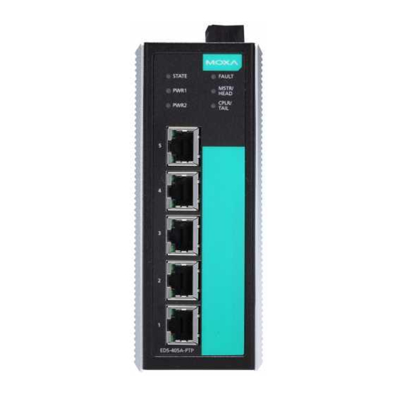
Overview The Moxa EtherDevice™ EDS-405A-PTP are 5-port 1588v2 PTP switches designed especially for real-time control applications. In addition, the built-in Modbus/TCP, PROFINET RT and EtherNet/IP help automation engineers to easily maintain an integrated SCADA control network.. Package Checklist The Moxa EDS-405A-PTP switches are shipped with the following items. If any of these items is missing or damaged, please contact your customer service representative for assistance. - Page 3 EDS-405A-PTP Panel Layout (standard) 1. Terminal block for power input PWR1/PWR2 and relay output 2. System state LED 3. Power input 1 LED 4. Power input 2 LED 5. Fault LED 6. MSTR/HEAD LED 7. CPLR/TAIL LED 8. 10/100BaseT(X) ports 9.
-
Page 4: Mounting Dimensions (Unit = Mm)
Mounting Dimensions (unit = mm) Unit = mm (inch) - 4 -... -
Page 5: Din-Rail Mounting
DIN-Rail Mounting The aluminum DIN-Rail attachment plate should already be fixed to the back panel of the EDS-405A-PTP when you take it out of the box. If you need to reattach the DIN rail attachment plate, make sure the stiff metal spring is situated towards the top, as shown in the following figures. -
Page 6: Wiring Requirements
Wiring Requirements WARNING Safety First! Be sure to disconnect the power cord before installing and/or wiring your Moxa EtherDevice Switch. Calculate the maximum possible current in each power wire and common wire. Observe all electrical codes dictating the maximum current allowable for each wire size. If the current goes above the maximum ratings, the wiring could overheat, causing serious damage to your equipment. -
Page 7: Wiring The Redundant Power Inputs
FAULT: The two middle contacts of the 6-contact terminal block connector are used to detect user-configured events. The two wires attached to the fault contacts form an open circuit when a user-configured event is triggered. If a user-configured event does not occur, the fault circuit remains closed. -
Page 8: Reset Button
10/100Base T(x) RJ45 Pinouts MDI Port Pinouts MDI-X Port Pinouts 8-pin RJ45 Signal Signal RJ45 (8-pin) to RJ45 (8-pin) Straight-Through Cable Wiring RJ45 (8-pin) to RJ45 (8-pin) Cross-Over Cable Wiring Reset Button The reset button is to reset the Ethernet switch to factory default settings by pressing and holding the reset button for 5 seconds. - Page 9 commercial switches—decreasing the possible loss caused by network failures in an industrial setting. There are 4 Hardware DIP Switches for Turbo Ring on the top panel of the EDS-405A-PTP that can be used to set up the Turbo Ring easily within seconds.
-
Page 10: Led Indicators
NOTE You must enable the Turbo Ring function first before using the DIP switch to activate the Master and Coupler functions. LED Indicators There are several LEDs on the EDS’s front panel. The function of each LED is described in the following table. Color State Description... -
Page 11: Auto Mdi/Mdi-X Connection
1. The switch’s coupling function is enabled to form a back-up path 2. When it’s set as the Tail of the Turbo Chain. 3. POST S.W. Fails (+Stat on and Fault blinking) 1. Turbo Chain is down. CPLR/TAIL GREEN 2. The switch is set as Turbo Chain’s Blinking Member and the corresponding chain port is down. - Page 12 STATE, CPLR/TAIL and MSTR/HEAD Relay Contact One relay output with current carrying capacity of 1A @ 24 VDC DIP Switches Master, Coupler, Turbo Ring, Reserve Power Input Voltage 12/24/48 VDC (9.6 to 60 VDC), redundant dual inputs Input Current (@ 24 V) Max.
Need help?
Do you have a question about the EtherDevice EDS-405A-PTP Series and is the answer not in the manual?
Questions and answers