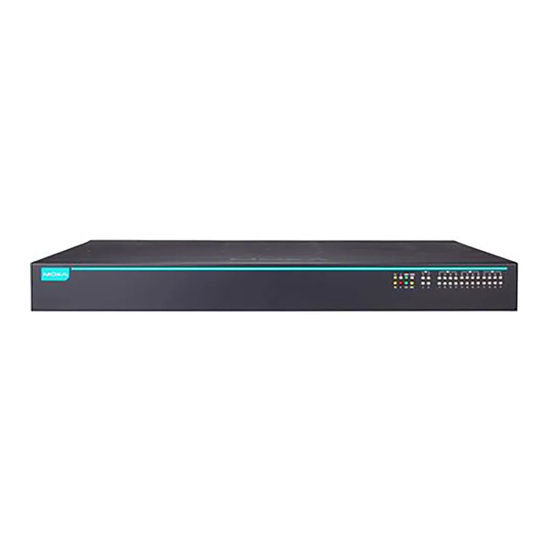
Summary of Contents for Moxa Technologies RKS-G4028 Series
- Page 1 RKS-G4028/ RKS-4028-L3 Series Quick Installation Guide Version 1.4, June 2024 Technical Support Contact Information www.moxa.com/support 2024 Moxa Inc. All rights reserved. P/N: 1802040000044 *1802040000044*...
-
Page 2: Package Checklist
Package Checklist The Moxa RKS-G4028/RKS-G4028-L3 industrial rackmount switch is shipped with the following items. If any of these items are missing or damaged, please contact your customer service representative for assistance. • RKS-G4028/RKS-G4028-L3 switch • 4 protective caps for unused SFP ports (only for RKS-G4028-GS models) •... - Page 3 Dimensions RM-G4000 Ethernet Interface Modules 4MSC2TX 4MST2TX 4SSC2TX 2MSC4TX 2MST4TX 2SSC4TX 6MSC 6MST - 3 -...
- Page 4 6SSC 8PoE 8GPoE 8SFP 8GSFP 8GTX WARNING When end users are using Optical SFP Communications modules, these must be limited to Laser Class 1. WARNING Use of the controls or adjustments or the performance of procedures other than those specified herein may result in hazardous radiation exposure.
-
Page 5: Wiring Requirements
Connecting the Power Inputs The RKS-G4028 Series switches support various types of power supply. • LV models provide one 24/48 VDC power input • 2LV models provide two 24/28 VDC power inputs • HV models provide one 110/220 VDC/VAC power input •... -
Page 6: Wiring The Relay Contact
LV Models Power Terminal Blocks 1. Insert the negative/positive (-/+) DC wires into the terminals. 2. Insert the terminal block connector prongs into the terminal block receptor. NOTE In order to have higher levels of protection against surge, it is suggested to install a surge protector in front of the power input of the PoE powered device so that it is suitable for use in IEC 61850 conditions. -
Page 7: Usb Connection
FAULT: The relay contact of the 2-pin terminal block connector is used to detect user-configured events. The two wires attached to the fault contacts form an open circuit when a user-configured event is triggered. If a user-configured event does not occur, the fault circuit remains closed. USB Connection Use Moxa’s USB Automatic Backup Configurator ABC-02- USB to connect to the USB storage port to backup and... -
Page 8: Led Indicators
unauthorized persons accessing the modules. If the stickers are broken, users will know the modules have been accessed by unauthorized persons. The figure below highlights the locations of the screws. Follow these steps to place the stickers. 1. Use a cloth to clean the surface of the screws with 75% alcohol solution. - Page 9 Color State Description 1. After pressing the reset button for 5 seconds the system is ready to do a Blinking factory reset. (4 Hz) 2. When the external storage ABC-02 or ABC-03 automatic backup device is connected to the switch. The system has initially failed in the boot-up process.
- Page 10 Color State Description 1. The switch is not the Master of Turbo Ring 1 or Turbo Ring 2. The switch is not the Head of the Turbo Chain. 3. The switch is not the Manager of the MRP Ring. 1. The switch’s ring coupling or dual homing function is enabled.
- Page 11 Color State Description When the port is active and links at 10/100 Mbps. When the port’s data is being Amber Blinking transmitted at 10/100 Mbps. When the port is inactive or link down. When the port is active and links at 1,000 Mbps.
- Page 12 RM-G4000-8TX/8SFP/6MSC/6MST/6SSC/4MSC2TX/4MST2TX/ 4SSC2TX/2MSC4TX/2MST4TX/2SSC4TX Color State Description The corresponding port’s 100 Mbps link is active. Data is being transmitted at 100 Green Blinking Mbps. The corresponding port’s link is Copper inactive. (10/100 The corresponding port’s 10 Mbps Mbps) link is active. Data is being transmitted at 10 Amber Blinking Mbps.
-
Page 13: Specifications
PoE power has been shut off Blinking because power budget is low. 1. Power is not being supplied to a powered device (PD). 2. The port is not connected to an IEEE 802.3bt/at/af standard powered device (PD). RM-G4000-8PoE Color State Description The corresponding port’s 100 Mbps link is active. - Page 14 Modules There are 3 module slots on the switch. Users can select different types of modules to insert into the switch. The modules that can be selected include 8-port/6-port modules with 10/100/1000BaseT(X), 10/100BaseT(X), 100/1000BaseSFP, or 100BaseFX (SC/ST connector) interfaces. Alarm Contact 1 relay output with current carrying capacity of 2 Channels A @ 24 VDC...
- Page 15 Power Consumption RKS-G4028-LV/2LV models: (Max.) (Full modules • Max. 60.72 W @ 24 VDC installed) • Max. 60 W @ 48 VDC RKS-G4028-HV/2HV models: • Max. 60.5 W @ 110 VDC • Max. 63.8 W @ 220 VDC • Max. 62.2 W @ 110 VAC •...
-
Page 16: Rack Mounting Instructions
Shock IEC 60068-2-27 Vibration IEC 60068-2-6 Industrial IEC 62443-4-1, IEC 62443-4-2 Cybersecurity Warranty Warranty Period 5 years Details See www.moxa.com/warranty Rack Mounting Instructions 1. Elevated Operating Ambient: If installed in a closed or multi- unit rack assembly, the operating ambient temperature of the rack environment may be greater than room ambient. -
Page 17: Restricted Access Locations
ATTENTION When installing the device onto a rack, make sure that the input terminal block and protective terminal do not connect, or it may cause an electric shock. NOTE The rackmount ears can be equipped on the front or rear of Moxa RKS-G4028/RKS-G4028-L3 switch.


Need help?
Do you have a question about the RKS-G4028 Series and is the answer not in the manual?
Questions and answers