Moxa Technologies PT-7728 User Manual
Hide thumbs
Also See for PT-7728:
- User manual (120 pages) ,
- Hardware installation manual (9 pages) ,
- Manual (84 pages)
Table of Contents
Advertisement
Quick Links
Advertisement
Table of Contents

Related Manuals for Moxa Technologies PT-7728


Summary of Contents for Moxa Technologies PT-7728
- Page 1 Moxa PowerTrans Switch PT-7728 User’s Manual www.moxa.com/product First Edition, February 2008 Moxa Inc. Tel: +886-2-8919-1230 Fax: +886-2-8919-1231 Web: www.moxa.com Moxa Technical Support Worldwide: support@moxa.com The Americas support@usa.moxa.com...
-
Page 2: Copyright Notice
Moxa PowerTrans Switch PT-7728 User’s Manual The software described in this manual is furnished under a license agreement and may be used only in accordance with the terms of that agreement. Copyright Notice Copyright © 2008 Moxa Inc. All rights reserved. -
Page 3: Table Of Contents
Configuring Traffic Prioritization ................3-37 Using Virtual LAN ......................3-39 The Virtual LAN (VLAN) Concept ................ 3-39 Sample Applications of VLANs using PT-7728 ............. 3-41 Configuring Virtual LAN..................3-43 Using Multicast Filtering....................3-44 The Concept of Multicast Filtering ................. 3-44 Configuring IGMP Snooping .................. - Page 4 Configuring Bandwidth Management ..............3-51 Broadcast Storm Protection..................3-51 Traffic Rate Limiting Settings................. 3-51 Using Port Access Control....................3-52 Configuring Static Port Lock .................. 3-52 Configuring IEEE 802.1X..................3-53 Using Auto Warning ......................3-55 Configuring Email Warning..................3-56 Event Type ......................3-56 Email Setup ......................
-
Page 5: Chapter 1 Introduction
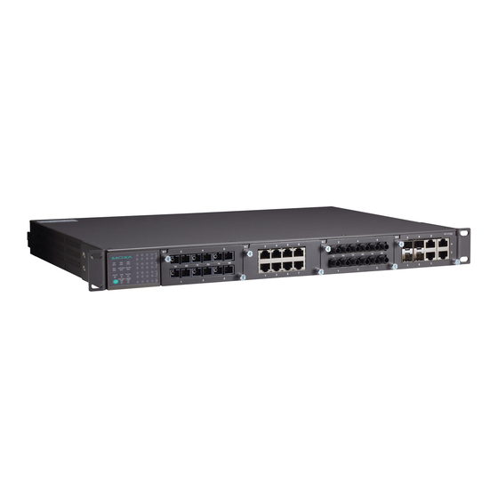
Introduction Chapter 1 Welcome to the PowerTrans PT-7728, a managed redundant Gigabit Ethernet switch designed especially for connecting Ethernet-enabled devices for industrial field applications. The following topics are covered in this chapter: Overview Package Checklist Software Features... -
Page 6: Overview
You can install up to 4 Gigabit Ethernet ports and 24 Fast Ethernet ports. Optional front or rear wiring makes the PT-7728 suitable for different applications. Package Checklist The PowerTrans PT-7728 is shipped with the following items. If any of these items is missing or damaged, please contact your customer service representative for assistance. 1 PowerTrans PT-7728 Hardware installation guide CD-ROM with user’s manual and SNMP MIB file... -
Page 7: Chapter 2 Getting Started
PT-7728's IP address, you can open the serial console by connecting the PT-7728 to a PC’s COM port with a short serial cable. You can open the Telnet or web console over an Ethernet LAN or over the Internet. -
Page 8: Serial Console Configuration (115200, None, 8, 1, Vt100)
Moxa website. Before running PComm Terminal Emulator, use an RJ45 to DB9-F (or RJ45 to DB25-F) cable to connect the PT-7728’s console port to your PC’s COM port (generally COM1 or COM2, depending on how your system is set up). - Page 9 115200 for Baud Rate, 8 for Data Bits, None for Parity, and 1 for Stop Bits. 4. On the Terminal tab, select VT100 for Terminal Type. Click OK. 5. In the terminal window, the PT-7728 will prompt you to select a terminal type. Enter 1 to select ansi/vt100 and press Enter.
-
Page 10: Configuration By Telnet Console
Configuration by Telnet Console You may open the PT-7728's Telnet or web console over a network. This requires that the PC host and PT-7728 are on the same logical subnet. You may need to adjust your PC host’s IP address and subnet mask. - Page 11 Ethernet cable. NOTE The PT-7728’s default IP address is 192.168.127.253. After making sure that the PT-7728 is connected to the same LAN and logical subnet as your PC, open the PT-7728's Telnet console as follows: 1. Click Start Run from the Windows Start menu.
- Page 12 5. In the terminal window, select Preferences… from the Terminal menu on the menu bar. 6. The Terminal Preferences window should appear. Make sure that VT100 Arrows is checked. 7. Use the following keys on your keyboard to navigate the PT-7728's Telnet console: Function Up, down, right, left arrow keys...
-
Page 13: Configuration By Web Browser
To connect to the PT-7728’s Telnet or web console, your PC host and the PT-7728 must be on the same logical subnet. NOTE If the PT-7728 is configured for other VLAN settings, you must make sure your PC host is on the management VLAN. NOTE When connecting to the PT-7728's Telnet or web console, first connect one of PT-7728’s... -
Page 14: Disabling Telnet And Browser Access
Disabling Telnet and Browser Access If you are connecting the PT-7728 to a public network but do not intend to manage it over the network, we suggest disabling both the Telnet and web consoles. This is done through the serial console, by navigating to System Identification under Basic Settings. -
Page 15: Chapter 3 Featured Functions
These functions can be accessed by serial, Telnet, or web console. The serial console can be used if you do not know PT-7728’s IP address and requires that you connect the PT-7728 to a PC COM port. The Telnet and web consoles can be opened over an Ethernet LAN or the Internet. -
Page 16: Configuring Basic Settings
PT-7728 User’s Manual Featured Functions Configuring Basic Settings Basic Settings includes the most common settings required by administrators to maintain and control the PT-7728. System Identification System Identification items are displayed at the top of the web console and will be included in alarm emails. -
Page 17: Password
ATTENTION By default, no password is assigned to the PT-7728’s web, Telnet, and serial consoles. If a password is assigned, you will be required to enter the password when you open the serial console, Telnet console, or Web console. -
Page 18: Accessible Ip
The PT-7728 uses an IP address-based filtering method to control access. You may add or remove IP addresses to limit access to the PT-7728. When the accessible IP list is enabled, only addresses on the list will be allowed access to the PT-7728. Each IP address and... -
Page 19: Port
PT-7728 User’s Manual Featured Functions Port Port settings are included to give the user control over port access, port transmission speed, flow control, and port type (MDI or MDIX). Enable Setting Description Factory Default Checked This allows data transmission through the port. -
Page 20: Network
10M-Half FDX Flow Ctrl This setting enables or disables flow control for the port when the port's Speed is set to Auto. The final result will be determined by the Auto process between the PT-7728 and connected devices. Setting Description... - Page 21 The PT-7728’s IP address will be assigned automatically by the network’s BootP server. Switch IP Address Setting Description Factory Default IP address for the PT-7728 This assigns the PT-7728's IP address on a 192.168.127.253 TCP/IP network. Switch Subnet Mask Setting Description...
-
Page 22: Time
NOTE The PT-7728 does not have a real time clock. The user must update the Current Time and Current Date to set the initial time for PT-7728 after each reboot, especially when there is no NTP server on the LAN or Internet connection. -
Page 23: System File Update-By Remote Tftp
This specifies the number of hours that the time None should be offset forward during Daylight Savings Time. System Up Time This indicates how long the PT-7728 remained up since the last cold start. The up time is indicated in seconds. Time Zone Setting Description... - Page 24 Setting Description Factory Default Max. 40 characters This specifies the path and file name of the None PT-7728’s configuration file on the TFTP server. Firmware Files Path and Name Setting Description Factory Default Max. 40 characters This specifies the path and file name of the None PT-7728’s firmware file.
-
Page 25: System File Update-By Local Import/Export
Export button to save the file. Upgrade Firmware To import a new firmware file onto the PT-7728, click Browse to select the firmware file that is saved on your computer. The upgrade procedure will proceed automatically after clicking Import. -
Page 26: Using Port Trunking
Port trunking can be used to combine up to 8 ports between two PT-7728 switches. If all ports on both switch units are configured as 100BaseTX and they are operating in full duplex, the potential bandwidth of the connection will be 1600 Mbps. -
Page 27: Configuring Port Trunking
PT-7728 User’s Manual Featured Functions Configuring Port Trunking The Port Trunking Settings page is where ports are assigned to a trunk group. Step 1: Select the desired Trunk Group (Trk1, Trk2, Trk3, Trk4). Step 2: Select the Trunk Type (Static or LACP). -
Page 28: Configuring Snmp
Configuring SNMP The PT-7728 supports SNMP V1, V2c, and V3. SNMP V1 and SNMP V2c use a community string match for authentication, which means that SNMP servers access all objects with read-only or read/write permissions using the community strings public and private by default. SNMP V3 requires that you select an authentication level of MD5 or SHA, and is the most secure protocol. -
Page 29: Snmp Read/Write Settings
For SNMP V3, there are two levels of privilege for different accounts to access the PT-7728. Admin privilege provides access and authorization to read and write the MIB file. User privilege allows reading of the MIB file only. -
Page 30: Trap Settings
PT-7728 User’s Manual Featured Functions Admin Auth. Type (for SNMP V1, V2c, V3, and V3 only) Setting Description Factory Default This allows the admin account to access No-Auth objects without authentication. Authentication will be based on the MD5- HMAC-MD5 algorithms. 8-character... -
Page 31: Private Mib Information
This is a particularly important feature for industrial applications, since it could take several minutes to locate the disconnected or severed cable. For example, if the PT-7728 is used as a key communications component of a production line, several minutes of downtime can result in a big loss in production and revenue. -
Page 32: The Turbo Ring Concept
PT-7728 User’s Manual Featured Functions NOTE Most managed switches by Moxa support two proprietary Turbo Ring protocols: Turbo Ring refers to the original version of Moxa’s proprietary redundant ring protocol, which has a recovery time of under 300 ms. Turbo Ring V2 refers to the new generation Turbo Ring, which has a recovery time of under 20 ms. - Page 33 PT-7728 User’s Manual Featured Functions Turbo Ring with even number of switches If the number of Ethernet switches in the Turbo Ring is 2N (an even number), the backup segment is one of the two segments connected to the (N+1)st switch (i.e., the unit directly opposite the master).
- Page 34 PT-7728 User’s Manual Featured Functions Determining the Redundant Path for Turbo Ring V2 For Turbo Ring V2, the backup segment is the Master segment connected to the 2nd redundant port on the master. Please refer to Configuring Turbo Ring V2 later in this chapter.
- Page 35 PT-7728 User’s Manual Featured Functions To configure the ring coupling for a Turbo Ring, select two PT series Ethernet switches (e.g., Switch A and B in the above figure) in the ring, and another two PT series Ethernet switches in the adjacent ring (e.g., Switch C and D).
-
Page 36: Configuring Turbo Ring And Turbo Ring V2
PT-7728 User’s Manual Featured Functions Dual-Homing Configuration for Turbo Ring V2 Dual-homing is only supported with Turbo Ring V2 and is used to connect two networks through a single Ethernet switch. The primary path is the operating connection, and the backup path is a back-up connection that is activated in the event that the primary path connection fails. - Page 37 This shows which communication protocol is in use: Turbo Ring, Turbo Ring V2, RSTP, or none. Master/Slave This indicates whether or not the PT-7728 is the master of the Turbo Ring. This field appears only for Turbo Ring or Turbo Ring V2. NOTE The user does not need to assign the master to use Turbo Ring or Turbo Ring V2.
- Page 38 Setting Description Factory Default This specifies that this PT-7728 Enable will be a ring coupler. Not checked This specifies that this PT-7728 is Disable not a ring coupler. Coupling Port Setting Description Factory Default This specifies which port on the...
- Page 39 This shows Healthy if the ring is operating normally, and shows Break if the ring’s backup link is active. Ring 1/2—Master/Slave This indicates whether or not the PT-7728 is the master of the Turbo Ring. This field appears only when selected to operate in Turbo Ring or Turbo Ring V2 mode. NOTE The user does not need to assign the master to use Turbo Ring or Turbo Ring V2.
- Page 40 Redundant Ports Setting Description Factory Default This specifies which port on the 1st Port PT-7728 will be used as the first None redundant port. This specifies which port on the 2nd Port PT-7728 will be used as the second None redundant port.
-
Page 41: The Stp/Rstp Concept
Networks that have a complicated architecture are prone to broadcast storms caused by unintended loops in the network. The PT-7728’s STP feature is disabled by default. To be completely effective, you must enable RSTP/STP on every PT-7728 connected to your network. - Page 42 PT-7728 User’s Manual Featured Functions If STP is enabled, it will detect duplicate paths and prevent, or block, one of them from forwarding traffic. In the following example, STP determined that traffic from LAN segment 2 to LAN segment 1 should flow through Bridges C and A because this path has a greater bandwidth and is therefore more efficient.
-
Page 43: How Stp Works
PT-7728 User’s Manual Featured Functions How STP Works When enabled, STP determines the most appropriate path for traffic through a network. The method is described below: STP Requirements Before STP can configure the network, the system must satisfy the following requirements: Communication must be established between all bridges. -
Page 44: Stp Example
PT-7728 User’s Manual Featured Functions STP Reconfiguration Once the network topology has stabilized, each bridge listens for "Hello" BPDUs that are transmitted from the Root Bridge at regular intervals. If a bridge does not receive a "Hello" BPDU after a certain interval (the Max Age time), the bridge assumes that the Root Bridge, or a link between itself and the Root Bridge, has gone down. -
Page 45: Using Stp On A Network With Multiple Vlans
PT-7728 User’s Manual Featured Functions Bridge A has been selected as the Root Bridge, since it was determined to have the lowest Bridge Identifier on the network. Since Bridge A is the Root Bridge, it is also the Designated Bridge for LAN segment 1. Port 1 on Bridge A is selected as the Designated Bridge Port for LAN Segment 1. -
Page 46: Configuring Stp/Rstp
This field shows which communication protocol is being used—Turbo Ring, RSTP, or neither. Root/Not Root This field appears only for RSTP mode. It indicates whether or not this PT-7728 is the Root of the Spanning Tree (the root is determined automatically). - Page 47 This specifies the amount of time to wait for a user "hello" message from the root before the PT-7728 will reconfigure itself as a root. When two or more devices on the network are recognized as a root, the devices will renegotiate to set up a new Spanning Tree topology.
-
Page 48: Using Traffic Prioritization
Quality of Service for your network. The rules define different types of traffic and specify how each type should be treated as it passes through the switch. The PT-7728 can inspect both IEEE 802.1p/1Q layer 2 CoS tags, and even layer 3 TOS information to provide consistent classification of the entire network. -
Page 49: How Traffic Prioritization Works
How Traffic Prioritization Works Traffic prioritization uses the four traffic queues that are present in your PT-7728 to ensure that high priority traffic is forwarded on a different queue from lower priority traffic. This is what provides Quality of Service (QoS) to your network. - Page 50 3 TOS enabled prioritization scheme. Traffic Prioritization The PT-7728 classifies traffic based on layer 2 of the OSI 7 layer model, and the switch prioritizes received traffic according to the priority information defined in the received packet. Incoming traffic is classified based upon the IEEE 802.1D frame and is assigned to the appropriate priority...
-
Page 51: Configuring Traffic Prioritization
PT-7728’ QoS capability improves your industrial network’s performance and determinism for mission critical applications. QoS Classification The PT-7728 supports inspection of layer 3 TOS and/or layer 2 CoS tag information to determine how to classify traffic packets. Queuing Mechanism Setting... -
Page 52: Cos Mapping
PT-7728 User’s Manual Featured Functions Inspect COS Setting Description Factory Default Enable/Disable This enables or disables the PT-7728 to inspect the Enable 802.1p COS tag in the MAC frame to determine the priority of each frame. CoS Mapping Setting Description... -
Page 53: Using Virtual Lan
49 to 64: High Using Virtual LAN Setting up Virtual LANs (VLANs) on your PT-7728 increases the efficiency of your network by dividing the LAN into logical segments, as opposed to physical segments. In general, VLANs are easier to manage. -
Page 54: Benefits Of Vlans
In a single VLAN defined on the PT-7728 In several VLANs simultaneously using 802.1Q tagging The standard requires that you define the 802.1Q VLAN ID about each VLAN on your PT-7728 before the switch can use it to forward traffic: Managing a VLAN A new or initialized PT-7728 contains a single VLAN—the Default VLAN. -
Page 55: Sample Applications Of Vlans Using Pt-7728
Featured Functions VLANs: Tagged and Untagged Membership The PT-7728 supports 802.1Q VLAN tagging, a system that allows traffic for multiple VLANs to be carried on a single physical (backbone, trunk) link. When setting up VLANs you need to understand when to use untagged and tagged membership of VLANs. Simply put, if a port is on a single VLAN it can be an untagged member, but if the port needs to be a member of multiple VLANs, tagged membership must be defined. - Page 56 PT-7728 User’s Manual Featured Functions In this application, Port 1 connects a single untagged device and assigns it to VLAN 5; it should be configured as Access Port with PVID 5. Port 2 connects a LAN with two untagged devices belonging to VLAN 2. One tagged device with VID 3 and one tagged device with VID 4.
-
Page 57: Configuring Virtual Lan
PT-7728 User’s Manual Featured Functions Configuring Virtual LAN VLAN Settings To configure 802.1Q VLAN on the PT-7728, use the VLAN Setting page to configure the ports. Management VLAN ID Setting Description Factory Default VLAN ID from 1 This assigns the VLAN ID of this PT-7728. -
Page 58: Using Multicast Filtering
PT-7728 User’s Manual Featured Functions Fixed VLAN List (Tagged) Setting Description Factory Default VID range from 1 This field will be active only when selecting the Trunk None to 4094 port type. Set the other VLAN ID for tagged devices that connect to the Trunk port. -
Page 59: Benefits Of Multicast
PT-7728 User’s Manual Featured Functions Benefits of Multicast The benefits of using IP multicast are that it: Uses the most efficient, sensible method to deliver the same information to many receivers with only one transmission. Reduces the load on the source (for example, a server) since it will not need to produce several copies of the same data. - Page 60 Query Mode Query mode allows the PT-7728 to work as the Querier if it has the lowest IP address on the subnetwork to which it belongs. IGMP querying is enabled by default on the PT-7728 to help prevent interoperability issues with some multicast routers that may not follow the lowest IP address election method.
-
Page 61: Configuring Igmp Snooping
Static Multicast MAC Some devices may only support multicast packets, but not support either IGMP Snooping or GMRP. The PT-7728 supports adding multicast groups manually to enable multicast filtering. Enabling Multicast Filtering Use the serial console or Web interface to enable or disable IGMP Snooping and IGMP querying. -
Page 62: Igmp Snooping Settings
VLAN. Snooping Enabled Globally Querier Setting Description Factory Default Enable/Disable This enables or disables the PT-7728’s querier function. Enabled if IGMP Snooping is Enabled Globally Static Multicast Router Port Setting Description Factory Default Select/Deselect This selects the ports that will connect to the multicast Disabled routers. -
Page 63: Add Static Multicast Mac
Featured Functions IGMP Table The PT-7728 displays the current active IGMP groups that were detected. The information includes VID, Auto-learned Multicast Router Port, Static Multicast Router Port, Querier Connected Port, and the IP and MAC addresses of active IGMP groups. -
Page 64: Configuring Gmrp
For example, so-called “broadcast storms” could be caused by an incorrectly configured topology, or a malfunctioning device. The PT-7728 not only prevents broadcast storms, but can also be configured to a different ingress rate for all packets, giving administrators full control of their limited bandwidth to prevent undesirable effects caused by unpredictable faults. -
Page 65: Configuring Bandwidth Management
PT-7728 User’s Manual Featured Functions Configuring Bandwidth Management Broadcast Storm Protection Setting Description Factory Default Enable/Disable This enables or disables Broadcast Storm Protection for Enable unknown broadcast packet globally. This enables or disables Broadcast Storm Protection for Disable unknown multicast packets globally. -
Page 66: Using Port Access Control
IEEE 802.1X. Static Port Lock The PT-7728 can also be configured to protect static MAC addresses for a specific port. With the Port Lock function, these locked ports will not learn any additional addresses, but only allow traffic from preset static MAC addresses, helping to block hackers and careless usage. -
Page 67: Configuring Ieee 802.1X
The UDP port of the RADIUS server 1812 Shared Key Setting Description Factory Default alphanumeric A key to be shared between the external RADIUS server None (Max. 40 and PT-7728. Both ends must be configured to use the characters) same key. 3-53... - Page 68 IEEE 802.1X for one or more ports. All end stations must enter usernames and passwords before access to these ports is allowed. 802.1X Re-Authentication The PT-7728 can force connected devices to be re-authorized manually. 802.1X Re-Authentication Setting Description Factory Default Enable/Disable This enables or disables 802.1X Re-Authentication...
-
Page 69: Using Auto Warning
The PT-7728 supports different approaches to warn engineers automatically, such as email and relay output. It also supports two digital inputs to integrate sensors into your system to automate alarms by email and relay output. -
Page 70: Configuring Email Warning
Email Alarm Events setting subsection). 2. Configuring Email Settings To configure PT-7728’s email setup from the serial, Telnet, or web console, enter your Mail Server IP/Name (IP address or name), Account Name, Account Password, Retype New Password, and the email address to which warning messages will be sent. -
Page 71: Email Setup
Warning e-mail messages will have sender given in the form: Moxa_PowerTrans_Switch_0001@Switch_Location where Moxa_PowerTrans_Switch is the default Switch Name, 0001 is PT-7728’s serial number, and Switch_Location is the default Server Location. Refer to the Basic Settings section to see how to modify Switch Name and Switch Location. -
Page 72: Configuring Relay Warning
Select the desired Event types from the Console or Web Browser Event type page (a description of each event type is given later in the Relay Alarm Events setting subsection). 2. Activate your settings After completing the configuration procedure, you will need to activate your PT-7728’s Relay Event Types. 3-58... -
Page 73: Event Setup
Events are related to the overall function of the switch, whereas Port Events are related to the activity of a specific port. The PT-7728 supports two relay outputs. You can configure which relay output is related to which events. This helps administrators identify the importance of the different events. -
Page 74: Warning List
DHCP Client or RARP protocol. In effect, PT-7728 acts as a DHCP server by assigning a connected device with a specific IP address stored in its internal memory. Each time the connected device is switched on or rebooted, PT-7728 sends the device the desired IP address. -
Page 75: Configuring Set Device Ip
STEP 2 Configure PT-7728’s Set device IP function, either from the Console utility or from the Web Browser interface. In either case, you simply need to enter the Desired IP for each port that needs to be configured. -
Page 76: Using Diagnosis
Take the following steps to set up the Mirror Port function: STEP 1 Configure PT-7728’s Mirror Port function from either the Console utility or Web Browser interface. You will need to configure three settings: Select the port number of the port whose network activity will be Monitored Port monitored. -
Page 77: Ping
The function’s most unique feature is that even though the ping command is entered from the user’s PC keyboard, the actual ping command originates from PT-7728 itself. In this way, the user can essentially sit on top of PT-7728 and send ping commands out through its ports. -
Page 78: Monitor By Port
Using the MAC Address Table This section explains the information provided by PT-7728’s MAC address table. The MAC Address table can be configured to display the following PT-7728 MAC address groups. Select this item to show all PT-7728 MAC addresses... -
Page 79: Using Event Log
This field shows the port that this MAC address belongs to Using Event Log Bootup This field shows how many times the PT-7728 has been rebooted or cold started. Date The date is updated based on how the current date is set in the Basic Setting page. -
Page 80: Using Syslog
PT-7728 User’s Manual Featured Functions Using Syslog This function provides the event logs for the syslog server. The function supports 3 configurable syslog servers and syslog server UDP port numbers. When an event occurs, the event will be sent as a syslog UDP packet to the specified syslog servers. - Page 81 PT-7728 User’s Manual Featured Functions NOTE The following events will be recorded into the PT-7728’s Event Log table, and will then be sent to the specified Syslog Server: Cold start Warm start Configuration change activated Power 1/2 transition (Off On), Power 1/2 transition (On...
- Page 82 MIB Groups Appendix A The PT-7728 comes with built-in SNMP (Simple Network Management Protocol) agent software that supports cold/warm start trap, line up/down trap, and RFC 1213 MIB-II. The standard MIB groups that the PT-7728 supports are as follows: MIB II.1 – System Group sysORTable MIB II.2 –...
- Page 83 PT-7728 User’s Manual MIB Groups MIB II.10 – Transmission Group dot3 dot3StatsTable MIB II.11 – SNMP Group SnmpBasicGroup SnmpInputStats SnmpOutputStats MIB II.17 – dot1dBridge Group dot1dBase dot1dBasePortTable dot1dStp dot1dStpPortTable dot1dTp dot1dTpFdbTable dot1dTpPortTable dot1dTpHCPortTable dot1dTpPortOverflowTable pBridgeMIB dot1dExtBase dot1dPriority dot1dGarp qBridgeMIB dot1qBase...
- Page 84 PT-7728 User’s Manual MIB Groups The PT-7728 also provides a private MIB file, located in the file Moxa-PT7728-MIB.my on the PT-7728 utility CD-ROM. Public Traps Cold Start Link Up Link Down Authentication Failure dot1dBridge New Root dot1dBridge Topology Changed Private Traps...
- Page 85 Specifications Appendix B Technology Standards IEEE 802.3 for 10BaseT, IEEE 802.3u for 100BaseT(X) and 100BaseFX, IEEE 802.3ab for 1000BaseT(X), IEEE 802.3z for 1000BaseSX/LX/LHX/ZX, IEEE 802.3x for Flow Control, IEEE 802.1D for Spanning Tree Protocol, IEEE 802.1w for Rapid STP, IEEE 802.1Q for VLAN Tagging, IEEE 802.1p for Class of Service, IEEE 802.1X for Authentication, IEEE 802.3ad for Port Trunk with LACP...
-
Page 86: Appendix B Specifications
PT-7728 User’s Manual Specifications Optical Fiber (100BaseFX) 100BaseFX Multi Mode Single Mode Single Mode, 80 km Wavelength 1300 nm 1310 nm 1550 nm Max. TX -10 dBm 0 dBm 0 dBm Min. TX -20 dBm -5 dBm -5 dBm RX Sensitivity... - Page 87 PT-7728 User’s Manual Specifications Connection 10-pin terminal block Overload Current Protection Present Reverse Polarity Protection Present Mechanical Casing IP30 protection Dimensions 440 x 44 x 325 mm (17.32 x 1.73 x 12.80 in.) (W x H x D) Installation 19-inch rack mounting Environmental Operating Temp.
Need help?
Do you have a question about the PT-7728 and is the answer not in the manual?
Questions and answers