Moxa Technologies MDS-G4000 Series Quick Installation Manual
Hide thumbs
Also See for MDS-G4000 Series:
- Quick installation manual (18 pages) ,
- Quick installation manual (26 pages)

Subscribe to Our Youtube Channel
Related Manuals for Moxa Technologies MDS-G4000 Series


Summary of Contents for Moxa Technologies MDS-G4000 Series
- Page 1 MDS-G4000/MDS-G4000-L3 Series Quick Installation Guide Version 1.3, August 2022 Technical Support Contact Information www.moxa.com/support 2022 Moxa Inc. All rights reserved. P/N: 1802040000005 *1802040000005*...
-
Page 2: Package Checklist
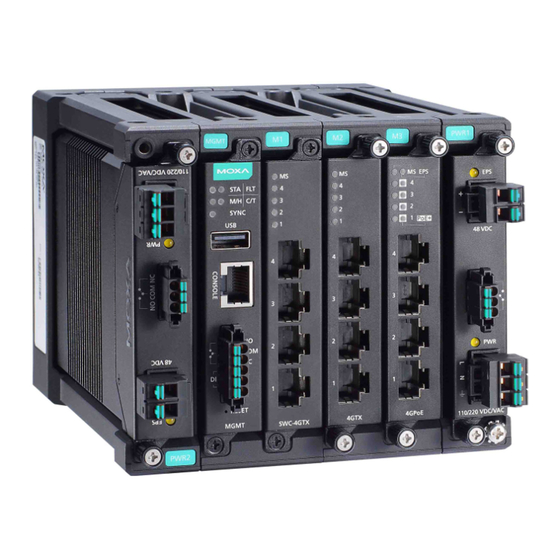
Package Checklist Moxa’s MDS-G4000/MDS-G4000-L3 Series industrial m odular DIN-rail switch is shipped with the following items. If any of these items are m issing or damaged, please contact your customer service representative for assistance. • 1 MDS-G4000 or MDS-G4000-L3 Series switch •... - Page 3 3. Module status 4. Switch and Control m odule slot 1 (Embedded) 5. Ethernet m odule slot 2 6. Ethernet m odule slot 3 7. Ethernet m odule slot 4 (For MDS-G4020/28, MDS-G4020/28-L3) 8. Ethernet m odule slot 5 (For MDS-G4020/28, MDS-G4020/28-L3) 9.
-
Page 4: Ethernet Modules
Ethernet Modules (Hardware Rev.2.0.0 and above) NOTE Transceivers for the LM-7000H-4GSFP module are sold separately. Refer to Supported SFP Modules for list of supported transceivers. LM-7000H-4GTX LM-7000H-4GSFP LM-7000H-4GPoE LM-7000H-4TX LM-7000H-4PoE Power Modules (Hardware Rev.2.1.0 and above) NOTE The PWR-LV-P48 power m odule is certified for Hazardous Location use. - Page 5 MDS-G4020/28 and MDS-G4020/28-L3 Series Insert the upper lip of the DIN rail into the DIN-rail m ounting kit. Press the device towards the DIN rail until it snaps into place. Pull down the two latches one by one to release the DIN-rail kit and lift up to rem ove the device from the DIN rail.
- Page 6 Rack-mounting Dimensions and Instructions (Optional: RK-3U-01) The rack m ount kit is designed for two MDS-G4028 or MDS-G4028-L3 products. Assemble the right and left part of the kit (indicated with No. 1 in the diagram) with four screws each. Assemble the part of the rack kit (indicated with No. 2 in the diagram ) with eight screws in order to combine two MDS-G4028 or MDS-G4028-L3 products.
-
Page 7: Matters That Require Attention
Rack Mount Front View Rack Mount Rear View Matters That Require Attention 1. Elevated Operating Temperature: If installed in a closed or m ulti-unit rack assembly, the operating ambient temperature of the rack environment m ay be greater than room temperature. Therefore, consideration should be given to installing the equipment in an environment compatible with the maximum am bient temperature (Tm a) specified by the manufacturer. - Page 8 ATTENTION Safety First! Be sure to disconnect the power cord before installing and/or wiring your Ethernet Switch. Calculate the m aximum possible current in each power wire and common wire. Observe all electrical codes dictating the maximum current allowable for each wire size.
-
Page 9: Power Terminal Blocks
ATTENTION For Hazardous Location Use The PoE capacity of the PWR-LV-P48 is only certified for use in hazardous locations up to a m aximum power budget of 369.6 W and a m axim um output of up to 15.4 W per port. For the PWR-HV-NP, the 110/220 VAC/VDC power supplies provide power to the switch. -
Page 10: Wiring The Relay Contact
PoE Power Terminal Blocks 1. Rem ove 8 to 9 m m of the DC wires’ protective cover. 2. Use a tool to push the spring mechanism inwards to open it. 3. Insert the negative/positive (-/+) DC wires into the terminals. 4. -
Page 11: Digital Input/Output
FAULT: The relay contact of the 3-pin terminal block connector is used to detect user-configured events. The m odule provides normally open and norm ally closed circuits depending on what the user chooses. For pin definitions refer to the table below. Relay Connection Power Off Boot up Ready Event Trigger... - Page 12 NOTE The default m odule is 4GTX, if it is the first tim e you are m ounting a 4TX, PoE, or SFP m odule, please reboot the switch after inserting it. The hot-swappable function, as defined above, will only work after the device is rebooted for the first tim e.
-
Page 13: Usb Connection
NOTE Using a shielded cable achieves better electromagnetic resistance. NOTE When grounding, we suggest using the cable type - AWG (Am erican Wire Gauge) 16 (1.31 mm RS-232 with RJ45 Interface Console Connection The switch has an RS-232 serial console with an RJ45 interface. Use a Moxa 9-pin fem ale console cable to connect to your PC's COM port (or via USB-to-Serial converters or hubs). -
Page 14: Led Indicators
LED Indicators The function of each LED is described in the table below. Color State Description System LEDs Norm al operation. Green Blinking 1. The system is booting up. (STATE) The system failed to initialize. 1. Switch failed to initialize. 2. - Page 15 SWC-4GTX Color State Description Norm al operation. Green Blinking This m odule is booting up. The m odule is out of service. (Module 1. The m odule failed to initialize. State) 2. A m odule designed for a different m odel was inserted. When the port is active and links on 1,000 Mbps.
- Page 16 LM-7000H-4GTX/LM-7000H-4GSFP/LM-7000H-4TX Color State Description Norm al operation. Green Blinking This m odule is booting up. The m odule is out of service. (Module 1. The m odule failed to initialize. State) 2. A m odule designed for a different m odel was inserted. When the port is active and links on at 100 Mbps.
- Page 17 LM-7000H-4GPoE/LM-7000H-4PoE Color State Description Norm al operation. Green Blinking The m odule is booting up. This m odule is out of service. 1. The m odule failed to initialize. 2. A user inserted a m odule designed (Module State) for a different model. 3.
-
Page 18: Specifications
PWR-HV-P48/PWR-LV-P48 Color State Description External power is being supplied to EPS (External Am ber the m odule's EPS input. Power Supply) No external power supply for PoE. Power is being supplied to the m odule's power input. Am ber Power is not being supplied to the m odule's power input. - Page 19 When using PWR-HV-P48: Power Consumption 110 VDC: 12.43 W (without 220 VDC: 12.87 W m odules 110 VAC: 13.42 W consumption) 220 VAC: 14.08 W When using PWR-LV-P48: 24 VDC: 12.67 W 48 VDC: 13.2 W Power LM-7000H-4GTX: 3.63 W Consumption of LM-7000H-4GPoE: 3.8 W m odule...
- Page 20 Weight MDS-G4012/MDS-G4012-L3 Series: 2.00 kg (4.41 lb) MDS-G4020/MDS-G4020-L3 Series: 2.50 kg (5.51 lb) MDS-G4028/MDS-G4028-L3 Series: 2.84 kg (6.26 lb) LM-7000H-4GSFP: 0.3 kg (0.66 lb) LM-7000H-4GTX: 0.24 kg (0.53 lb) LM-7000H-4GPoE: 0.31 kg (0.69 lb) LM-7000H-4TX: 0.24 kg (0.53 lb) LM-7000H-4PoE: 0.31 kg (0.69 lb) PWR-HV-P48/PWR-LV-P48: 0.36 kg (0.69 lb) PWR-HV-NP/PWR-LV-NP: 0.34 kg (0.75 lb) Installation...
-
Page 21: Supported Sfp Modules
Warranty Warranty Period 5 years Details See www.moxa.com/warranty Supported SFP Modules Module Description SFP-1FEMLC-T SFP m odule with 1 100Base multi-mode, LC connector for 2/4 km transmission, -40 to 85°C operating temperature SFP-1FESLC-T SFP m odule with 1 100Base single-mode with LC connector for 40 km transmission, -40 to 85°C operating temperature SFP-1FELLC-T... - Page 22 Module Description SFP-1G40ALC-T WDM-type (BiDi) SFP m odule with 1 1000BaseSFP port with LC connector for 40 km transmission; TX 1310 nm, RX 1550 nm, -40 to 85°C operating tem perature SFP-1G40BLC WDM-type (BiDi) SFP m odule with 1 1000BaseSFP port with LC connector for 40 km transmission;...
-
Page 23: Restricted Access Locations
Module Description SFP-1GTXRJ45-T SFP m odule with 1 1000BaseT port with RJ45 connector for 100 m transmission, -40 to 75°C operating temperature Note: This m odule is not certified for Hazardous Location. Restricted Access Locations • This equipment is intended to be used in Restricted Access Locations, such as a computer room, with access lim ited to service personnel or users who have been instructed on how to handle the m etal chassis of equipment that is very hot. - Page 24 Hazardous Location Usage Terms Usage Terms Models MDS-G4012, MDS-G4012-T MDS-G4020, MDS-G4020-T MDS-G4028, MDS-G4028-T Rating Input: 24 to 48 VDC, 3.3 A (for PWR input) and 48 VDC, 8.2 A (for EPS input) Relay Output: 30 VDC/1 A Digital Input: 30 VDC/8 m A PoE Output: 48 VDC, 15.4 W per port Conductors ≧105°C...
Need help?
Do you have a question about the MDS-G4000 Series and is the answer not in the manual?
Questions and answers