Subscribe to Our Youtube Channel
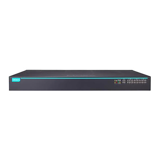
Summary of Contents for Moxa Technologies RKS-G4028 Series
- Page 1 RKS-G4028/ RKS-4028-L3 Series Quick Installation Guide Version 1.1, August 2022 Technical Support Contact Information www.moxa.com/support 2022 Moxa Inc. All rights reserved. P/N:1802040000041 *1802040000041*...
-
Page 2: Package Checklist
Package Checklist The Moxa RKS-G4028/RKS-G4028-L3 industrial rackmount switch is shipped with the following items. If any of these items are missing or dam aged, please contact your customer service representative for assistance. • RKS-G4028/RKS-G4028-L3 switch • 4 protective caps for unused SFP ports (only for RKS-G4028-GS m odels) •... - Page 3 Dimensions RM-G4000 Ethernet Interface Modules 4MSC2TX 4MST2TX 4SSC2TX 2MSC4TX 2MST4TX 2SSC4TX 6MSC 6MST - 3 -...
- Page 4 6SSC 8PoE 8GPoE 8SFP 8GSFP 8GTX WARNING When end users are using Optical SFP Communications m odules, these must be lim ited to Laser Class 1. WARNING Use of the controls or adjustments or the performance of procedures other than those specified herein may result in hazardous radiation exposure.
-
Page 5: Wiring Requirements
Connecting the Power Inputs The RKS-G4028 Series switches support various types of power supply. • LV m odels provide one 24/48 VDC power input • 2LV m odels provide two 24/28 VDC power inputs • HV m odels provide one 110/220 VDC/VAC power input •... -
Page 6: Wiring The Relay Contact
LV Models Power Terminal Blocks 1. Insert the negative/positive (-/+) DC wires into the terminals. 2. Insert the terminal block connector prongs into the terminal block receptor. NOTE In order to have higher levels of protection against surge, it is suggested to install a surge protector in front of the power input of the PoE powered device so that it is suitable for use in IEC 61850 conditions. -
Page 7: Usb Connection
FAULT: The relay contact of the 2-pin terminal block connector is used to detect user-configured events. The two wires attached to the fault contacts form an open circuit when a user-configured event is triggered. If a user-configured event does not occur, the fault circuit remains closed. USB Connection Use Moxa’s USB Automatic Backup Configurator ABC-02- USB to connect to the USB host port to backup and restore... -
Page 8: Led Indicators
Follow these steps to place the stickers. 1. Use a cloth to clean the surface of the screws with 75% alcohol solution. 2. We suggest you use a tweezer to place the stickers. 3. Press the stickers down with 15PSI (pound per square inch) for at least 15 seconds. -
Page 9: State Description
Color State Description When the system has successfully booted up and no events have been triggered. The switch is set as the Master of the Turbo Ring, or as the Head of the Turbo Chain, or as the Root of the RSTP. 1. - Page 10 Color State Description When the port is active and links at 1,000 Mbps. Green When the port’s data is being Blinking M1 SFP transmitted at 1,000 Mbps. (100/1000 When the port is inactive or link down. Mbps, 4GS When the port is active and links at 100 model Mbps.
- Page 11 RM-G4000-8TX/8SFP/6MSC/6MST/6SSC/4MSC2TX/4MST2TX/ 4SSC2TX/2MSC4TX/2MST4TX/2SSC4TX Color State Description The corresponding port’s 100 Mbps link is active. Green Blinking Data is being transmitted at 100 Mbps. Copper The corresponding port’s link is inactive. (10/100 The corresponding port’s 10 Mbps link is Mbps) active. Am ber Blinking Data is being transmitted at 10 Mbps.
-
Page 12: Specifications
RM-G4000-8PoE Color State Description The corresponding port’s 100 Mbps link is active. Green Blinking Data is being transmitted at 100 Mbps. Copper The corresponding port’s link is (10/100/ inactive. 1000 The corresponding port’s 10 Mbps link Mbps) is active. Am ber Blinking Data is being transmitted at 10 Mbps. - Page 13 Standards IEEE 802.1D-2004 for Spanning Tree Protocol IEEE 802.1p for Class of Service IEEE 802.1Q for VLAN Tagging IEEE 802.1s for Multiple Spanning Tree Protocol IEEE 802.1w for Rapid Spanning Tree Protocol IEEE 802.1X for Authentication IEEE 802.3 for 10BaseT IEEE 802.3ab for 1000BaseT(X) IEEE 802.3ad for Port Trunk with LACP IEEE 802.3u for 100BaseT(X) and 100BaseFX...
-
Page 14: Warranty
Weight RKS-G4028-LV/HV Models: 4,900 g RKS-G4028-2LV/2HV Models: 5,200 g RKS-G4028-PoE-LV/HV Models: 5,000 g RKS-G4028-PoE-2LV/2HV Models: 5,300 g RM-G4000-8TX: 300 g RM-G4000-8SFP: 400 g RM-G4000-8GTX: 300 g RM-G4000-8GSFP: 400 g RM-G4000-6MSC: 400 g RM-G4000-6MST: 400 g RM-G4000-6SSC: 400 g RM-G4000-4MSC2TX: 400 g RM-G4000-4MST2TX: 400 g RM-G4000-4SSC2TX: 400 g RM-G4000-2MSC4TX: 400 g... -
Page 15: Rack Mounting Instructions
Rack Mounting Instructions 1. Elevated Operating Ambient: If installed in a closed or multi- unit rack assembly, the operating ambient temperature of the rack environment m ay be greater than room ambient. Therefore, consideration should be given to installing the equipment in an environment compatible with the maximum ambient temperature (Tm a) specified by the manufacturer. -
Page 16: Restricted Access Locations
ATTENTION When installing the device onto a rack, m ake sure that the input terminal block and protective terminal do not connect, or it m ay cause an electric shock. NOTE The rackm ount ears can be equipped on the front or rear of Moxa RKS-G4028/RKS-G4028-L3 switch.


Need help?
Do you have a question about the RKS-G4028 Series and is the answer not in the manual?
Questions and answers