Table of Contents
Advertisement
Quick Links
Advertisement
Table of Contents

Related Manuals for TESTO 6457


Summary of Contents for TESTO 6457
- Page 1 6457 COMPRESSED AIR METER Instruction manual...
-
Page 3: Table Of Contents
Table of contents 1 GENERAL INFORMATION ................5 1.1 Incoming goods inspection, transportation and storage ......5 • Make sure that the packaging is undamaged! ..........5 • Make sure that the contents are not damaged!...........5 • If you have any questions, please contact your supplier or their sales office. - Page 4 Table of contents 4.3.4 Consumption quantity monitoring [ImP] ........ 19 4.3.4.1 Meter reading ............19 4.3.4.2 Counter reset ............19 4.3.4.3 Consumption quantity monitoring via pulse signals........... 20 4.3.4.4 Consumption quantity monitoring via preset counter ..........20 4.3.5 Measuring value damping ............. 21 4.3.6 Low flow cut-off ..............
- Page 5 Explanation submenu DIS ................43 7.8 Submenu COLR, SIM ................44 Explanation submenu COLR ................ 45 Explanation submenu SIM ................45 8 COMMISSIONING ..................46 9 PARAMETER SETTING ................46 9.1 General parameter setting ..............47 9.1.1 Select submenu ..............47 9.1.2 Change to the process value display (RUN mode) ....
- Page 6 Table of contents 9.6.1 Read min/max values ............56 9.6.2 Simulation ................56 10 OPERATION ....................57 11 TROUBLESHOOTING ................57 12 MAINTENANCE, REPAIR AND DISPOSAL ..........59 13 CONFIGURATION AND FACTORY SETTINGS ........60 13.1 Configuration of OUx on delivery ............60 13.2 Factory setting ..................
-
Page 7: General Information
GENERAL INFORMATION Incoming goods inspection, transportation and storage • Make sure that the packaging is undamaged! Inform your supplier of any damage to the packaging. Retain the damaged packaging until the matter is settled. • Make sure that the contents are not damaged! Inform your supplier of any damage to the contents. -
Page 8: Safety Precautions
SAFETY PRECAUTIONS Read this instruction manual before commissioning the compressed air meter. Store this instruction manual in a location that is accessible for all users at all times. Intended use The compressed air meter is intended exclusively for use in pipe systems for working compressed air, provided that the calibration certificate does not explicitly allow use with other gases. -
Page 9: Installation, Commissioning And Operation
Installation, commissioning and operation The compressed air meter was built and tested reliably according to state-of-the-art technology and left the factory in an appropriately safe condition. As the user, you are responsible for compliance with all valid safety regulations, including: •... -
Page 10: Exclusion Of Liability
Exclusion of liability Liability of the manufacturer and its vicarious agents shall exist only in the event of deliberate acts or gross negligence. The extent of liability shall be limited to the value of the respective order placed with the manufacturer. The manufacturer shall accept no liability for damages that occur due to non-observance of the safety instructions or non-compliance with the instruction manual or the operating conditions. -
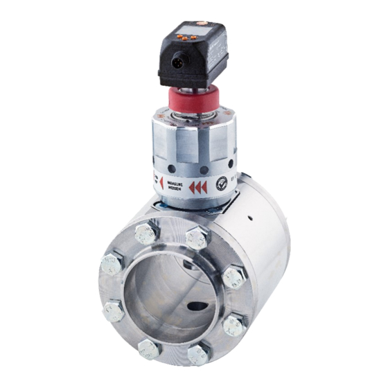
Page 11: Design And Function / Scope Of Delivery
DESIGN AND FUNCTION / SCOPE OF DELIVERY Overview of components Sensor unit Straight pin as alignment aid Dummy plug Hexagon socket head screw M 10 Dummy plug holder both sides Direction of flow arrow Measuring station Brass sealing plug Hexagon screw depending on DN Viton O-rings Compac steel welding neck flange Compac stainless steel sealing... -
Page 12: Electric Sensor Unit Quick-Change Fitting
Electric sensor unit quick-change fitting The sensor records the standard volumetric flow of working compressed air based on the calorimetric measuring principle. It detects the four process parameters flow velocity, flow quantity, consumption quantity and media temperature. All specifications apply to standard volumetric flow according to DIN ISO 2533 (1013 mbar, 15 °C, 0% relative air humidity). -
Page 13: Aluminium Quick-Change Fitting With Compac Flange
Aluminium quick-change fitting with Compac flange The aluminium quick-change fitting accommodates the sensor unit and enables maintenance without interrupting the flow, with reproducible positioning of the measuring point. The upper closure of the quick-change fitting is provided by a sealing cone. -
Page 14: Measuring Station
Measuring station The measuring station with Compac welding neck flanges is used to precision-mount the electronic volume flow sensor. The measuring station is welded into pipelines with the Compac welding neck flanges in line with the direction of flow (see engraved direction arrow). The nominal width of the measuring station and welding neck flanges must match the nominal pipe width ( see 3). -
Page 15: Technical Data
TECHNICAL DATA Thermal mass flow sensor The thermal mass flow sensor for compressed air volume flow measurement works independently of the process pressure and media temperature. Sensor Thermal glass-coated ceramic sensor Media Compressed air, with special calibration also CO2, N2 Accuracy Class 1-5-1: ±... -
Page 16: Accessories
Switching and pulse signal overload-proof DIN EN 60947-5-9 Accessories Replacement sensor 4.2.1 The replacement sensor serves as a replacement in case of damage to or loss of the original mass flow sensor. When ordering a new sensor, please indicate the certificate number of the old sensor in order to take account of customer- specific measuring conditions directly during calibration. -
Page 17: Sensor Parameter Setting For Co2 And N2
• Sensor parameter setting for CO2 and N2 Six measuring points are parametrised with specified nominal widths, standard temperatures and pressures for nitrogen or carbon dioxide, then moved to the test stand where the standard volume is tested. Function ▪ The flow is monitored by a calorimetric measuring system, the measuring signals are evaluated by the electronics. -
Page 18: Switching Output
OFF (output switched to high impedance) Pulse output 4.3.2 Switching output OUTx changes its switching status if it is above or below the set switching limits (flow or temperature). Hysteresis or window function can be selected. Example of flow monitoring: Hysteresis function Window function SP = Switching point... -
Page 19: Analog Output
4.3.3 Analog output The instrument provides an analog signal that is proportional to the flow quantity or the media temperature. Within the measuring range, the analog signal is between 4 and 20 mA. The measuring range is scalable: ▪ [ASP2] determines at which measured value the output signal is 4 mA. - Page 20 Fig. 1 Analog output characteristic according to standard IEC 60947-5-7. Analog signal Measured value (flow or temperature) Detection range Display range Measuring range Scaled measuring range Flow Temperature MAW: Zero/lower range value for non-scaled measuring range. (When a low flow cut-off is set for Q: Signal output starting at MAW + LFC ( 4.3.6) MEW:...
-
Page 21: Consumption Quantity Monitoring [Imp]
4.3.4 Consumption quantity monitoring [ImP] The instrument has an internal quantity counter (= totaliser). It continuously totals up the consumption quantity and provides this process value on the display. Pulse signals or a switching signal (preset counter) can be used to monitor the consumption quantity. -
Page 22: Consumption Quantity Monitoring Via Pulse Signals
4.3.4.3 Consumption quantity monitoring via pulse signals The output emits a pulse signal each time the flow quantity (pulse value) set under [ImPS] is reached. OUT1 and OUT2 cannot be used simultaneously for the pulse output. Note 4.3.4.4 Consumption quantity monitoring via preset counter The output emits a switching signal when the flow quantity set under [ImPS] is reached. -
Page 23: Measuring Value Damping
4.3.5 Measuring value damping The damping time [dAP.F] can be used to set after how many seconds the output signal reaches 63% of the final value in the event of a sudden change in the flow value. The set damping time stabilizes the switching outputs, the analog outputs and the display. -
Page 24: Colour Of The Characters In The Display
4.3.8 Colour of the characters in the display The colour of the characters in the display can be set via the parameter [coL.x]: ▪ Permanent definition of the display colour: – bk/wh (black/white) – yellow − green – ▪ Colour change from red to green or vice versa: –... -
Page 25: Installation
INSTALLATION Installation may only be carried out by authorised, qualified staff, e.g. pipeline engineers. Please observe the relevant national regulations. The electrical connections are to be performed by a WARNING qualified electrician. To install and remove the sensor the line must be depressurized. -
Page 26: Length Measurements Of The Compressed Air Meter
Length measurements of the compressed air Number of screws n Through holes DL Direction of flow meter KMAT Ø Inch D0x (steel) / D1x Part no. (stainless steel) -
Page 27: Installation Position
Installation position Do not install the sensor in the crossed-out installation positions shown in the following graphic in point 6. Otherwise, in the event of limited flow, the specified accuracy cannot be maintained. The arrow shows the direction of flow for the medium. 1, 2: Vertical installation position, any instrument 3, 4: Horizontal installation position, any instrument Left installation position, instrument lying sideways... -
Page 28: Required Measuring Section
Required measuring section Take account of the required inflow and outflow section in order to achieve the specified measuring accuracy. The inflow section refers to the pipeline length upstream of the compressed air meter and the outflow section to the pipeline length Note downstream of the compressed air meter, as seen in the direction of flow for the medium. -
Page 29: Installation Of The Compressed Air Meter
Installation of the compressed air meter To avoid a mixed seam in the welded joint to the pipeline, make sure that the Compac flanges are made of steel or stainless steel according to the pipeline. Note To install and remove the sensor the line must be depressurized. -
Page 30: Installing The Sensor In The Measuring Station
3. Screw the measuring station between the flanges according to the direction of flow. Fix the screws in diagonal order for even force distribution. 5.6.2 Installing the sensor in the measuring station Make sure that the pipeline is depressurized before installing the sensor. -
Page 31: Sensor Replacement
If this is not the case, the measuring station has to be turned between the flanges. 5. Fix the sensor to the interchangeable fitting with the union nut and without tools. 6. The mechanical installation of the compressed air meter is now complete. -
Page 32: Electrical Connection
1. Turn the quick-change fitting manually to the service end position. To operate the quick-change fitting, turn the adjusting nut anti-clockwise as far as it will go in the direction of "SERVICE CLOSE – ZU" to bring the quick-change fitting into the "Service position" and thus close it. 2. -
Page 33: 4-Wire Pin Assignment
5.8.1 4-wire pin assignment If you are using the standard connection, the following pin assignment applies to the connection cable or the pin assignment directly on the sensor. Pin no. Wire colour Assignment Brown +L (18-30 V DC) Green OUT2 Yellow 0 V DC (GND) White... -
Page 34: 5-Wire Pin Assignment (Accessory)
5.8.2 5-wire pin assignment (accessory) If the optional connecting cable for electrical isolation is used ( 4.2.2), then the following assignments apply. Pin no. Wire colour Assignment Brown + L (19 to 30 V DC) sensor supply Pink + potential-free pulse output (collector) OUT1 White - potential-free pulse output (emitter) OUT1 Green... -
Page 35: Operation And Display Elements
Operation and display elements The following illustration shows the operating and display unit of the sensor from above. 1 and 2: Switching status LEDs ▪ LED = switching status OUT1 (lights up if output 1 is switched) = switching status OUT2 (lights up if output 2 is switched) ▪... -
Page 36: Menu
MENU Process value display (RUN) It is possible to switch between three process value displays during operation. ▪ Press the [▲] or [▼] key ▪ The display switches between the standard indication and two other views. ▪ After 30 seconds, the instrument switches back to the standard display. -
Page 37: Main Menu
Main menu Process value display (RUN) Explanation of the parameters 7.4 Submenu OUT1 and 7.5 Submenu OUT2 The displayed parameters change when the factory setting in submenu OUT1 and OUT2 is changed. -
Page 38: Extended Functions Ef
Extended functions EF Main menu Parameter Explanation and setting options Restore factory setting Reset the totaliser Display instrument information Configuration output 1 Configuration output 2 Configuration basic settings Display min. / max. process values Configuration display view Configuration display colour Configuration simulation mode... -
Page 39: Submenu Out1
Submenu OUT1 Main menu... - Page 40 Parameter Explanation and setting options Standard measurement parameter for evaluation by OUT1: SEL 1 FLOW or TEMP Output function for OUT1: ▪ Flow: Hno, Hnc, Fno, Fnc, ImP Temperature: Hno, Hnc, Fno, Fnc ▪ Hno = Switching signal with hysteresis function normally open Hnc = Switching signal with hysteresis function normally closed Fno = Switching signal with window function normally open Fnc = Switching signal with window function normally closed...
-
Page 41: Submenu Out2
Submenu OUT2 Main menu The displayed parameters change when the factory settings are changed in submenu OUT2. Note... - Page 42 Parameter Explanation and setting options Standard measurement parameter for evaluation by OUT2: SEL 2 FLOW or TEMP Output function for OUT1: ▪ Flow: Hno, Hnc, Fno, Fnc, I, ImP Temperature: Hno, Hnc, Fno, Fnc, I ▪ Hno = Switching signal with hysteresis function normally open Hnc = Switching signal with hysteresis function normally closed Fno = Switching signal with window function normally open Fnc = Switching signal with window function normally closed...
-
Page 43: Submenu Cfg
Submenu CFG Main menu Parameter Explanation and setting options uni.F Standard unit of measurement for flow uni.T Standard unit of measurement for temperature Measured value damping for flow dAP.F Switching logic for outputs Low flow cut-off Standard pressure to which measured and display values for rEF.P flow refer. -
Page 44: Submenu Mem, Dis
Submenu MEM, DIS Main menu... -
Page 45: Explanation Submenu Mem
Explanation submenu MEM Parameter Explanation and setting options Lo.F Minimum value of the flow volume measured in the process Hi.F Maximum value of the flow volume measured in the process Minimum value of the temperature measured in the process Lo.T Hi.T Maximum value of the temperature measured in the process Explanation submenu DIS... -
Page 46: Submenu Colr, Sim
Submenu COLR, SIM Main menu... -
Page 47: Explanation Submenu Colr
Explanation submenu COLR The displayed parameters change when the factory settings in submenu OUT1 and OUT2 are changed. Note Parameter Explanation and setting options coL.F Colour of the characters in the display for the flow value cFH.F Upper limit value for the colour change for flow measurement dFL.F Lower limit value for the colour change for flow measurement coL.T... -
Page 48: Commissioning
COMMISSIONING After power-on and expiry of the readiness delay time of approx. 1 second, the instrument is in RUN mode (=normal operating mode). It carries out its measurement and evaluation functions and generates output signals according to the set parameters. ▪... -
Page 49: General Parameter Setting
General parameter setting 1. Change from RUN mode to the main menu [●] 2. Select the required parameter [▲] or [▼] [●] 3. Change to setting mode 4. Change the parameter value [▲] or [▼] > 1s 5. Acknowledge the set parameter value [●] 6. -
Page 50: Timeout
Unlocking: Make sure that the instrument is in normal operating mode. ▪ ▪ Press [▲] and [▼] simultaneously for 10 seconds until [ Reset menu lock] is displayed 9.1.4 Timeout If no key is pressed for 30 seconds while setting a parameter, the instrument returns to the operating mode with the value unchanged. -
Page 51: Analog Signal Flow Out2
9.2.3 Analog signal flow OUT2 Menu OUT2: Select [SEL2] and set FLOW [SEL2] ▪ ▪ Select [ou2] and set analog signal: [ou2] I (4 to 20 mA) [ASP2] ▪ Select [ASP2] and set the value at which 4 mA is provided. ▪... -
Page 52: Quantity Monitoring By Preset Counter Out1 Or Out2
9.3.2 Quantity monitoring by preset counter OUT1 or OUT2 Menu OUTx: ▪ Select [SELx] and set FLOW [SELx] [oux] ▪ Select [oux] and adjust the pulse output: ImP [ImPSx] ▪ Select [ImPSx] and set the flow quantity at which output x switches. [ImPRx] ▪... -
Page 53: Counter Reset Using An External Signal
9.3.6 Counter reset using an external signal Menu OUT2: [ou2] ▪ Select [rTo] and set In.D. ▪ Select [Din2] and set counter reset signal: [Din2] HIGH = reset for high signal LOW = reset for low signal +EDG = reset for rising edge -EDG = reset for falling edge →... -
Page 54: Analog Signal Temperature Out2
[FHx] ▪ Select [FHx] and set the value at which the output switches. [FLx] ▪ Select [FLx] and set the value at which the output resets. 9.4.3 Analog signal temperature OUT2 Menu OUT2: ▪ Select [SEL2] and set Temp [SEL2] [ou2] ▪... -
Page 55: Standard Unit Of Measurement For Flow
9.5.2 Standard unit of measurement for flow Menu CFG ▪ Select [uni.F] and set the unit of measurement for [uni.F] standard display ( 7.1): l/min, m /h, m/s, ft /m,ft /h, ft/s The consumption quantity (meter reading) is automatically displayed with the unit of measurement that provides the highest accuracy. -
Page 56: Standard Conditions
9.5.7 Standard conditions Menu CFG ▪ Select [rEF.P] and set standard pressure. [rEF.P] ▪ Select [rEF.T] and set standard temperature. [rEF.T] 9.5.8 Colour of the characters in the display Menu COLR: ▪ Select [coL.F] for flow or [coL.T] for temperature and set [coL.x] the colour of the characters for the process value in the standard display:... -
Page 57: Error Behaviour Of The Outputs
9.5.10 Error behaviour of the outputs Menu OUT1: ▪ Select [FOU1] and set error behaviour for output 1: [FOU1] = Output 1 switches ON in the event of an error. = Output 1 switches OFF in the event of an error. = Output 1 switches irrespective of the error as defined with the parameters Menu OUT2:... -
Page 58: Diagnostic Functions
Diagnostic functions 9.6.1 Read min/max values Menu MEM: Select [Lo.x] or [Hi.x] to display the highest or lowest [Lo.x] ▪ process value measured: [Hi.x] [Lo.F] = Minimum value of the flow volume measured in the process. [Hi.F] = Maximum value of the flow volume measured in the process. -
Page 59: Operation
OPERATION The process values to be permanently displayed can be preset 9.5.1 Standard display). A standard unit of measurement can be defined for the flow measurement and the temperature measurement 9.5.2 and 9.5.3). In addition to the preset standard display, the display can be changed by pressing [▲] or [▼] 7.1 Process value display (RUN). - Page 60 Description Troubleshooting ERROR Temp. Error in Check temperature Error temperature measurement. Replace measurement instrument cr.OL Critical Critical Check flow range / over exceeding of the temperature range limit detection range cr.UL Critical Critical Check temperature under undershooting of range limit the detection range* Short...
-
Page 61: Maintenance, Repair And Disposal
Warning LED flashes LED flashes rapidly MAINTENANCE, REPAIR AND DISPOSAL As a rule, no maintenance measures are necessary. ▪ Define regular calibration intervals according to process requirements. Recommendation: every 12 months. The instrument may only be repaired by the manufacturer. ▪... -
Page 62: Configuration And Factory Settings
CONFIGURATION AND FACTORY SETTINGS 13.1 Configuration of OUx on delivery Menu Parameter Configuration User setting OUT1 SEL1 FLOW OUT2 FLOW SEL2 Nominal width ImPS1 ASP2 … AEP DN65 0 … 2000 m DN80 0 … 2750 m DN100 10 m 0 …... - Page 63 Menu Parameter Factory setting User setting OUT2 FLOW SEL2 ASP2 AEP2 100% SP1/FH1 rP1/FL1 ImPS2 0.0001 m ImPR2 Dln2 +EDG FOU2 uni.F uni.T °C dAP.F 0,6 s 0,13% rEF.T 15 °C rEF.P 1013 mbar diS/L diS/U diS/R diS/B COLR coL.F bk/wh coL.T bk/wh...
- Page 64 0970 6457 en 01...
Need help?
Do you have a question about the 6457 and is the answer not in the manual?
Questions and answers