Sign In
Upload
Manuals
Brands
TESTO Manuals
Measuring Instruments
6457
TESTO 6457 Manuals
Manuals and User Guides for TESTO 6457. We have
1
TESTO 6457 manual available for free PDF download: Instruction Manual
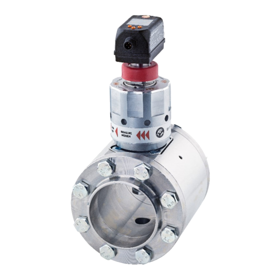
TESTO 6457 Instruction Manual (64 pages)
COMPRESSED AIR METER
Brand:
TESTO
| Category:
Measuring Instruments
| Size: 2 MB
Table of Contents
Table of Contents
3
1 General Information
7
Incoming Goods Inspection, Transportation and Storage
7
Make Sure that the Packaging Is Undamaged
7
Make Sure that the Contents Are Not Damaged
7
If You Have any Questions, Please Contact Your Supplier or Their Sales Office
7
2 Safety Precautions
8
Read this Instruction Manual before Commissioning the Compressed Air
8
Meter. Store this Instruction Manual in a Location that Is Accessible for All Users at All Times
8
Intended Use
8
Installation, Commissioning and Operation
9
Regulations, Including
9
The Authorised Personnel Must Have Read and Understood this Instruction Manual and Comply with the Instructions Set out in It
9
Exclusion of Liability
10
3 Design and Function / Scope of Delivery
11
Electric Sensor Unit Quick-Change Fitting
12
Absolute Measuring Range
12
Aluminium Quick-Change Fitting with Compac Flange
13
Compac Welding Neck Flange (V Flange) Steel
13
Dummy Plug
13
Measuring Station
14
ISO Calibration Certificate
14
4 Technical Data
15
Thermal Mass Flow Sensor
15
Output Signals
15
Accessories
16
Replacement Sensor
16
Connecting Cable with Electric Isolation
16
Calibration Options
16
ISO Certificate
16
Sensor Parameter Setting for CO2 and N2
17
Function
17
Processing the Measuring Signals
17
Switching Output
18
Analog Output
19
Consumption Quantity Monitoring [Imp]
21
Meter Reading
21
Counter Reset
21
Consumption Quantity Monitoring Via Pulse Signals
22
Consumption Quantity Monitoring Via Preset Counter
22
Measuring Value Damping
23
Low Flow Cut-Off
23
Simulation
23
Colour of the Characters in the Display
24
5 Installation
25
Determining the Installation Point
25
Well Accessible with Low Vibration
25
Length Measurements of the Compressed Air Meter
26
Installation Position
27
Required Measuring Section
28
Direction of Flow
28
Installation of the Compressed Air Meter
29
Installation of the Measuring Station
29
Installing the Sensor in the Measuring Station
30
Sensor Replacement
31
Electrical Connection
32
4-Wire Pin Assignment
33
X Pulse Output, 1 X Analog Output (Condition on Delivery)
33
5-Wire Pin Assignment (Accessory)
34
6 Operation
34
Thermal Mass Flow Sensor
34
Operation and Display Elements
35
7 Menu
36
Process Value Display (RUN)
36
Main Menu
37
Extended Functions EF
38
Submenu OUT1
39
Submenu OUT2
41
Submenu CFG
43
Submenu MEM, DIS
44
Explanation Submenu MEM
45
Explanation Submenu DIS
45
Submenu COLR, SIM
46
Explanation Submenu COLR
47
Explanation Submenu SIM
47
8 Commissioning
48
9 Parameter Setting
48
General Parameter Setting
49
Select Submenu
49
Change to the Process Value Display (RUN Mode)
49
Lock / Unlock
49
Timeout
50
Settings for Flow Monitoring
50
Limit Value Monitoring OUT1 or OUT2 / Hysteresis Function
50
Limit Value Monitoring OUT1 or OUT2 / Window Function
50
Analog Signal Flow OUT2
51
Settings for Consumption Quantity Monitoring
51
Quantity Monitoring by Pulse Signal OUT1 and OUT2
51
Quantity Monitoring by Preset Counter OUT1 or OUT2
52
Manual Counter Reset
52
Time-Controlled Counter Reset
52
Deactivating Counter Reset
52
Counter Reset Using an External Signal
53
Settings for Temperature Monitoring
53
Limit Value Monitoring OUT1 or OUT2 / Hysteresis Function
53
Limit Value Monitoring OUT1 or OUT2 / Window Function
53
Analog Signal Temperature OUT2
54
User Settings (Optional)
54
Standard Display
54
Standard Unit of Measurement for Flow
55
Standard Unit of Measurement for Temperature
55
Measuring Value Damping
55
Switching Logic for Outputs
55
Low Flow Cut-Off
55
Standard Conditions
56
Colour of the Characters in the Display
56
Switching/Reset Delay
56
Error Behaviour of the Outputs
57
Restore Factory Settings
57
Diagnostic Functions
58
Read Min/Max Values
58
Simulation
58
10 Operation
59
11 Troubleshooting
59
12 Maintenance, Repair and Disposal
61
13 Configuration and Factory Settings
62
Configuration of Oux on Delivery
62
Factory Setting
62
Advertisement
Advertisement
Related Products
TESTO 645
TESTO 6440
TESTO 6446
TESTO 6448
TESTO 606-2
TESTO Smart Probes 605i
TESTO 606-1
TESTO 6610
TESTO 635
TESTO Hygrotest 600 DHT
TESTO Categories
Measuring Instruments
Thermometer
Data Loggers
Thermal cameras
Test Equipment
More TESTO Manuals
Login
Sign In
OR
Sign in with Facebook
Sign in with Google
Upload manual
Upload from disk
Upload from URL