Table of Contents
Advertisement
Quick Links
Advertisement
Table of Contents

Related Manuals for TESTO 6448


Summary of Contents for TESTO 6448
- Page 1 6448 · Compressed air counter probe Instruction manual...
-
Page 3: Table Of Contents
1 Contents Contents Contents ....................3 Safety and the environment ..............5 2.1. About this document ................ 5 2.2. Safety ....................5 2.3. Protecting the environment .............. 7 Specifications ..................8 3.1. Use ....................8 3.2. Overview..................9 3.3. Technical data ................10 3.3.1. - Page 4 2 Safety and the environment 6.2. Calibration ..................43 Troubleshooting ..................44 7.1. Replacing damaged parts ............. 44 7.2. Replacing O-rings and seal rings ..........44 7.3. Error messages ................44...
-
Page 5: Safety And The Environment
2 Safety and the environment Safety and the environment 2.1. About this document Symbols and writing standards The following characters and symbols are used in this instruction manual to emphasise text passages that need special attention. Symbol Explanation Notes This arrow points out specifics that must be observed during operation. - Page 6 2 Safety and the environment The manufacturer has undertaken all necessary measures to ensure safe operation. The user must ensure that the instruments are set up and installed in such a way that their safe use is not affected. The instruments are factory-tested and were delivered in a safe condition.
-
Page 7: Protecting The Environment
Hand this documentation on to any subsequent users of the product. 2.3. Protecting the environment • At the end of its useful life, send the product to the separate collection for electric and electronic devices (observe local regulations) or return the product to Testo for disposal. -
Page 8: Specifications
3 Specifications Specifications 3.1. The compressed air counter is intended exclusively for use in pipe systems for working compressed air, provided that the calibration certificate does not explicitly allow use with other gases. Its design means that it can be operated in pressurised systems up to PN16 and with a tapping clamp from DN250 up to PN10. -
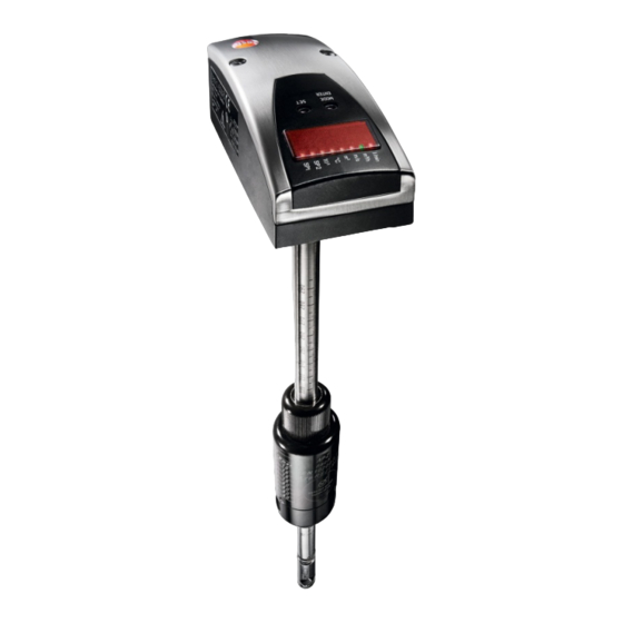
Page 9: Overview
3 Specifications 3.2. Overview 1 Tapping clamp (optional) 2 Measurement fitting with quick-release coupling (optional) 3 PBCOver reverse running protection 4 Compressed air bar probe 5 Drilling tool (optional) -
Page 10: Technical Data
3 Specifications 3.3. Technical data 3.3.1. Dimensions for the compressed air bar probe (mm) -
Page 11: Technical Data For The Compressed Air Bar Probe
3 Specifications 3.3.2. Technical data for the compressed air bar probe The thermal mass flow sensor for the compressed air volume flow measurement is independent of the process pressure and the media temperature. Sensor Sensor material Thermal, glass-coated ceramic sensor Measurement Calorimetric method... - Page 12 3 Specifications Inputs and outputs Analog outputs Output type 4 to 20 mA (4-wire), freely scalable between zero and the end of the measuring range for m³/min, m³/h, m/s and °C Max. 500 Ω Load Further outputs Pulse valence adjustable in increments of 1 Pulse output m³...
- Page 13 IEC 1000/4/4 burst 2 kV IEC 1000/4/6 10 V HF grid-bound Warranty 2 years, for warranty terms, see www.testo.com/warranty Compressed air (CO also possible with special calibration) Operating conditions Rel. humidity 〈90 %RH Humidity (sensors) Ambient 0 to +60 °C...
-
Page 14: Description & Technical Data - Accessories/Service
3 Specifications Measuring range for volumetric flow as per DIN2533 depending on pipe diameter Version Inner pipe Measuring range diameter in (160 m/s) DN 40 40.9 0 to 600 m³/h DN 50 53.1 0 to 1000 m³/h DN 65 70.3 0 to 1880 m³/h DN 80 82.5... -
Page 15: Ball Valve
The integrated ball valve enables the compressed air line to be isolated from the measuring instrument. The quick-release coupling is used to integrated an additional measuring point (e.g. the Testo dewpoint transmitter) Technical data for the measurement fitting Measurement fitting Brass, nickel-plated... -
Page 16: Drill Unit
3 Specifications 3.3.3.4. Drill unit The special drill unit, when used in conjunction with a ball valve and tapping clamp, enables the compressed air bar probe to be installed under pressure. An additional instruction manual is available for this and is provided with the drill. 3.3.3.5. -
Page 17: Initial Operation
4 Initial operation Initial operation 4.1. Mechanical assembly 4.1.1. Preparation Determining the installation point The installation point should be easily accessible and experience only low vibrations. The ambient temperature must not exceed the values specified in the technical data (pay attention to possible heat radiation). - Page 18 4 Initial operation Vertical installation Horizontal Horizontal installation position, direction of flow installation position, direction of flow horizontally to the left, position, direction horizontally to the rear, sensor downwards of flow vertically sensor to the left (heated downwards, sensor element upwards) sensor to the rear Vertical installation Horizontal...
- Page 19 4 Initial operation Direction of flow The direction of flow must be taken into account when installing the measurement fitting. This is shown on the tapping clamp by means of an arrow (Compac-Air system). The arrow points in the direction in which the medium in the pipeline flows.
-
Page 20: Assembly Of The Clamp
4 Initial operation On-site preparations The installation point must be freely accessible and there must be enough space to work around the pipes. A stable stepladder is required for all assembly work carried out up to 3.5 metres off the floor (height of the pipe). A working platform must be provided for work at greater heights. -
Page 21: Assembly Of The Measurement Fitting/Ball Valve
4 Initial operation Observe before and during assembly 1. Compare the pipe diameters and check the correct size of the clamp. 2. Before the clamp is assembled, always check the installation position of the sensor and the position of the clamp. -
Page 22: Checking The Clamp Leak-Tightness
4 Initial operation 4.1.4. Checking the clamp leak-tightness Tools: - Hearing protection - Pressurised cylinder with valve or compressed air pipe 1. Screw the compressed air bar probe on to the measurement fitting and tighten. 2. Connect the pressurised cylinder or compressed air pipe to the quick-release coupling. -
Page 23: Assembly Of The Pbcover Reverse Running Protection Unit
4 Initial operation 4.1.6. Assembly of the PBCOver reverse running protection unit 1 Work surface for 36 mm wrench 2 ½" thread 3 Adjustment screw 4 Sensor head 1. Seal the PBCOver reverse running protection with Teflon tape on the ½" thread. 2. -
Page 24: Electrical Connection
4 Initial operation 4.2. Electrical connection The instrument may only be installed by a qualified electrician. Follow the national and international regulations regarding the installation of electro-technical systems. The voltage supply is to be laid out in accordance with EN50178, SELV, PELV. To meet the "limited voltage"... - Page 25 4 Initial operation 2 x switching outputs Both of the available OUT1and OUT2 outputs are each used as a PNP signal output (pulse). Pin assignment on the instrument Five-wire pin assignment (accessory) If the optional connecting cable for electrical isolation is used (Connecting cable, page 16), then the following assignments apply.
- Page 26 4 Initial operation • So that the compressed air meter can display the correct volumetric flow, the inner pipe diameter must be set in the menu. Adjustable parameters, page 32, menu item dIA. • For the compressed air meter to output the measuring values as accurately as possible as an analog value, the analog output must be scaled.
-
Page 27: Operation
5 Operation Operation Thermal mass flow sensor Familiarise yourself with the operation and programming of the sensor. The sensor is calibrated ex factory and provided with default settings for each nominal width. Do not inadvertently change these. 5.1. Operation and display elements The following illustration shows the control and display unit of the sensor from above. -
Page 28: Types Of Operation
5 Operation Number Type Description Yellow LED = display of the switch status: LED illuminates when the respective output is switched through Four-digit Display of the current volume flow alphanumeric Display of the average speed display Display of the current consumption quantity Display of the parameters and parameter values Indication of the voltage level of the... - Page 29 5 Operation The totaliser (consumption quantity counter) periodically (every 10 minutes) stores interim values as well as the amount of time elapsed of the automatic reset. After a drop in voltage, this value is available as the current status of the totaliser (the possible loss of data can amount to a maximum of 10 minutes).
-
Page 30: Menu Overview
5 Operation 5.1.2. Menu overview Meaning and function of abbreviations: see following chapter. Character explanations: S = SET button, M = Mode/Enter button... -
Page 31: Programming
5 Operation 5.1.3. Programming Press [Mode/Enter] until the desired parameter appears in the display. Press and hold [Set]. The current parameter value flashes for 5 seconds. It is then increased steps by pressing once or continuously by pressing and holding the button). Press [Mode/Enter] briefly (confirmation). -
Page 32: Adjustable Parameters
5 Operation Condition at delivery: Not locked. When the instrument is locked, is shown briefly in the display if an attempt is made to change the parameter values. 5.1.4. Adjustable parameters Representation Description in display SPx (SP1, Switch point 1/2 SP2) Upper limit value at which the output changes its switch status. - Page 33 5 Operation Representation Description in display Configuration for output 1 5 functions can be set: = Hysteresis function / normally open (NO) = Hysteresis function / normally closed (NC) = Window function / normally open (NO) = Window function / normally closed (NC) Output signal for consumption quantity: = Pulse output Configuration for output 2...
- Page 34 5 Operation Representation Description in display Digital input +EDG = rising edge -EDG = falling edge HIGH = High level LOW = Low level When the set signal is detected at the output, the totaliser is zeroed (and the current value is saved - flashing value) Only active if OU2 = In.D Extended functions This menu point contains a submenu (EF2) with further...
- Page 35 5 Operation Representation Description in display FOUx (FOU1, Behaviour of output x in the event of an internal error. OU2) Adjustable parameters: On = output x switches ON in the event of an error. Off = output x switches OFF in the event of an error (With both values (On, Off), the meter no longer runs in the event of an error OU = output 1 switches as defined with the parameters...
- Page 36 5 Operation Representation Description in display Setting the display 7 settings can be selected: = update of measurement value every 50 ms = update of measurement value every 200 ms = update of measurement value every 600 ms The measurement value update affects only the display. It has no effect on the outputs.
- Page 37 5 Operation Representation Description in display SEL2 Standard measurement parameter for evaluation using output 2: • Limit value signal or analogue signal for flow • Limit value signal or analogue signal for temperature Low flow cut-off Select and set the limit value: Adjustment range: where LIM = 100%: 0.13% to 1% of meas.
-
Page 38: Setting The Preset Counter / Pulse Value (Imps)
5 Operation Representation Description in display rEF.P Standard pressure; measurement and display values for flow correspond to this value. Select rEF.P and set the desired standard pressure: Adjustment range: 950…1050 hPa in 1 hPa increments Standard: to 1013 hPa rEF.T Standard temperature;... - Page 39 5 Operation As soon as the first digit flashes, there are three options (flashes on grey background): Press [Set] briefly once The flashing digit is increased. 0 is displayed after 9. each time. [Set] pressed once [Set] pressed once [Set] pressed once Press and hold [Set].
- Page 40 5 Operation If the fourth digit flashes for 3 seconds without changing, then digit 1 is active when it is > 0. After 3 seconds If digit 1 is "0", then the display changes to the next lowest adjustment range. The decimal point is moved one space to the left or the LED display changes.
- Page 41 5 Operation The hysteresis is adjustable: First the switch point is determined, then the return switch point at the desired distance. Window function The window function allows a defined OK range to be monitored. If the flow fluctuates between switch point (SPx) and return switch point (rPx), the output is switched through (window function/NO contact) or opened (window function/NC contact).
- Page 42 5 Operation Factory setting Scaled measuring range The analogue end point (AEP) varies according to the selected parameters (inner diameter, standard temperature, standard pressure and scale factor). The output signal is between 4 and 20 mA in the set measuring range.
-
Page 43: Cleaning The Sensor
6 Cleaning the sensor Cleaning the sensor You must clean the sensor: • Before each calibration/inspection • Regularly during operation You can remove the sensor and clean it manually. • Only clean the sensor with approved cleaning agents. • Do not use any abrasive cleaning agents. These can lead to irreparable damages to the sensor. - Page 44 7 Troubleshooting Troubleshooting 7.1. Replacing damaged parts Damages to the compressed air counter that affect the pressure integrity may only be remedied by authorised personnel. After each repair, the technical data of the specifications must be checked by authorised personal, e.g. pressure test.
Need help?
Do you have a question about the 6448 and is the answer not in the manual?
Questions and answers