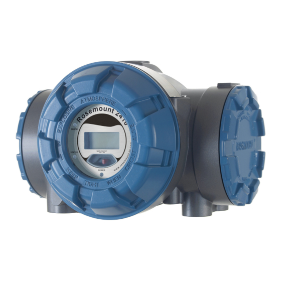
Emerson Rosemount 2410 Reference Manual
Tank hub
Hide thumbs
Also See for Rosemount 2410:
- Reference manual (184 pages) ,
- Instruction manual (34 pages) ,
- Instructions manual (30 pages)
Table of Contents
Advertisement
Advertisement
Table of Contents
Troubleshooting

Related Manuals for Emerson Rosemount 2410


Summary of Contents for Emerson Rosemount 2410
- Page 1 Reference Manual 00809-0100-2410, Rev EA December 2019 ™ Rosemount 2410 Tank Hub...
- Page 2 Read this manual before working with the product. For personal and system safety, and for optimum product performance, ensure you thoroughly understand the contents before installing, using, or maintaining this product. For equipment service or support needs, contact your local Emerson Automation Solutions/Rosemount Tank Gauging representative.
-
Page 3: Table Of Contents
Chapter 4 Configuration.......................63 4.1 Safety messages..........................63 4.2 Introduction........................... 64 4.3 Configuration tools........................64 4.4 Basic configuration of a Rosemount 2410 Tank Hub............... 65 4.5 Advanced configuration......................... 66 4.6 Configuration using TankMaster WinSetup..................66 Chapter 5 Operation........................69 5.1 Safety messages..........................69 5.2 Integral display.......................... - Page 4 C.3 Change the communication parameters for the primary bus............161 C.4 Open the secondary bus window....................162 C.5 Configure a virtual relay output....................162 C.6 Set up a Rosemount 2410 for hybrid density applications.............167 C.7 Volume configuration........................170 C.8 Arithmetic operations........................175 C.9 Configure the analog output......................
-
Page 5: Chapter 1 Introduction
Physical security is an important part of any security program and fundamental to protecting your system. Restrict physical access by unauthorized personnel to protect end users’ assets. This is true for all systems used within the facility. Rosemount 2410 Tank Hub... -
Page 6: Symbols
Introduction Reference Manual December 2019 00809-0100-2410 Symbols Table 1-1: Symbols The CE marking symbolizes the conformity of the product with the applicable European Community Directives. The EU-Type Examination Certificate is a statement of a Notified Certification Body declaring that this product meets the Essential Health and Safety Requirements of the ATEX directive The FM APPROVED Mark indicates that the equipment is approved by FM Approvals according to applicable Approval Standards and is applicable for... -
Page 7: Manual Overview
Chapter Configuration describes how to configure the Rosemount 2410 Tank Hub by using the TankMaster WinSetup configuration program. Chapter Operation describes the integral display and how to specify display variables. It... -
Page 8: Technical Documentation
Product data sheets • Rosemount Tank Gauging System Data Sheet (00813-0100-5100) • Rosemount 2460 System Hub Product Data Sheet (00813-0100-2460) • Rosemount 2410 Product Data Sheet (00813-0100-2410) • Rosemount 5900S Product Data Sheet (00813-0100-5900) • Rosemount 5900C Product Data Sheet (00813-0100-5901) •... -
Page 9: Service Support
Introduction 00809-0100-2410 December 2019 Service support For service support contact the nearest Emerson Automation Solutions /Rosemount Tank Gauging representative. Contact information can be found on the web site www.Emerson.com. Product recycling/disposal Recycling of equipment and packaging should be taken into consideration and disposed of in accordance with local and national legislation/regulations. - Page 10 Introduction Reference Manual December 2019 00809-0100-2410 Reference Manual...
-
Page 11: Chapter 2 Overview
Primary Bus Zone 0 The Rosemount 2410 is designed for use in hazardous area Zone 1 (Class 1, Division 1) and communicates with field devices in Zone 1 via the intrinsically safe Tankbus. The Rosemount 2410 is available in two versions for single tanks or multiple tanks. The multiple tanks version supports up to 10 tanks and 16 devices. -
Page 12: Communication
Primary Bus to a Rosemount 2460 System Hub. Data is buffered by the system hub and distributed to a TankMaster PC, or a host system, whenever the 2460 receives a request for data. In case no system hub is included in the system, the Rosemount 2410 Tank Hub can communicate directly with a host computer. - Page 13 Reference Manual Overview 00809-0100-2410 December 2019 Figure 2-2: Typical Configuration of a Rosemount 2410 and 2460 System Hub Connected to PC/Host A. Field devices B. Tankbus C. Rosemount 2410 D. Primary bus: TRL2 Modbus, RS485 Modbus E. Secondary bus: Enraf and others, HART 4-20 mA analog output/input F.
- Page 14 A THUM Adapter, connected to the Intrinsically Safe Secondary bus, allows wireless communication between a Rosemount 2410 Tank Hub and a Smart Wireless Gateway. Figure 2-4: Typical Configuration of a Rosemount 2410 with Wireless Connection to Smart Wireless Gateway and PC/Host A.
-
Page 15: Components
Reference Manual Overview 00809-0100-2410 December 2019 Components Figure 2-5: Rosemount 2410 Components A. Intrinsically safe terminal compartment B. Non-intrinsically safe terminal compartment C. Integral display (optional) D. Write protection switch E. Cable entries for IS connection (two ½ - 14 NPT) F. -
Page 16: System Overview
Overview Reference Manual December 2019 00809-0100-2410 System overview The Rosemount Tank Gauging system is a state-of-the art inventory and custody transfer radar tank level gauging system. It is developed for a wide range of applications at refineries, tank farms and fuel depots, and fulfills the highest requirements on performance and safety. - Page 17 Segment coupler Rosemount 2240S Temperature Transmitter Rosemount 644 Temperature Transmitter Rosemount 2230 Graphical Field Display Rosemount 5300 Level Transmitter Rosemount 2410 Tank Hub Rosemount 5408 Level Transmitter Rosemount 3051S Pressure Transmitter Custody transfer / Inventory tank gauging Rosemount TankMaster PC...
- Page 18 Figure 2-7: Rosemount Tank Gauging System Architecture for Wireless Systems A. Non-hazardous area B. Hazardous area C. Rosemount TankMaster PC D. Emerson Wireless 1420 Gateway E. Rosemount 2410 Tank Hub F. Tankbus G. Emerson Wireless 775 THUM Adapter H. Rosemount 5900S Radar Level Gauge I. Rosemount 2240S Temperature Transmitter J.
- Page 19 Rosemount 5900S Radar Level Gauge Segment coupler Rosemount 2240S Temperature Transmitter Rosemount 5300 Level Transmitter Rosemount 5408 Level Transmitter Rosemount 2230 Graphical Field Display Custody transfer / Inventory tank gauging Rosemount 3051S Pressure Transmitter Operational control Rosemount 2410 Tank Hub...
- Page 20 2.4.3 Rosemount 2410 Tank Hub The Rosemount 2410 Tank Hub acts as a power supply to the connected field devices in the hazardous area using the intrinsically safe Tankbus. The tank hub collects measurement data and status information from field devices on a tank.
- Page 21 00809-0100-2410 December 2019 There are two versions of the Rosemount 2410 Tank Hub; one for single tank operation and one for multiple tanks operation. The multiple tanks version of the Rosemount 2410 supports up to 10 tanks and 16 devices. With the Rosemount 5300 the Rosemount 2410 supports up to 5 tanks.
- Page 22 By using a Rosemount 3051S Pressure Transmitter near the bottom of the tank as a complement to a Rosemount 2410 Radar Level Gauge, the density of the product can be calculated and presented. One or more pressure transmitters with different scalings can be used on the same tank to measure vapor and liquid pressure.
-
Page 23: Installation Procedure
Installation procedure Follow these steps for a proper installation: Procedure 1. Review Mounting Considerations. Installation considerations. 2. Mount the Rosemount 2410 Tank Hub. Mechanical installation. 3. Wire the Rosemount 2410. Electrical installation. 4. Make sure covers and cable/conduit connections are tight. - Page 24 Overview Reference Manual December 2019 00809-0100-2410 Reference Manual...
-
Page 25: Chapter 3 Installation
Avoid contact with leads and terminals. • Ensure the main power to the Rosemount 2410 Tank Hub is off and the lines to any other external power source are disconnected or not powered while wiring the gauge. Rosemount 2410 Tank Hub... -
Page 26: Installation Considerations
The Rosemount 2410 Tank Hub can also be mounted on the tank roof if this is the preferred location. In case the tank hub is exposed to long periods of sunshine, a sunshade should be used to prevent it from being heated to temperatures above the maximum operating temperature. -
Page 27: Mechanical Installation
Reference Manual Installation 00809-0100-2410 December 2019 Mechanical installation The Rosemount 2410 is designed for mounting on a pipe stand or on a wall. 3.3.1 Pipe mounting Prerequisites Note Ensure that the Rosemount 2410 is installed to minimize vibration and mechanical shock. - Page 28 4. Secure the tank hub to the bracket by tightening the screw. 3.3.2 Wall mounting Prerequisites Note Ensure that the Rosemount 2410 is installed such that vibration and mechanical shock is minimized. Procedure 1. Mount the bracket on the wall by using four M8 screws and flat washers. Note Countersunk screws are not suitable.
- Page 29 Reference Manual Installation 00809-0100-2410 December 2019 2. Attach the tank hub to the bracket and tighten the screw. Rosemount 2410 Tank Hub...
-
Page 30: Electrical Installation
3.4.1 Cable entries The Rosemount 2410 electronics housing has four ½ - 14 NPT and two ¾ - 14 NPT entries. The connections must be made in accordance with local or plant electrical codes. Make sure that unused ports are properly sealed to prevent moisture or other contamination from entering the terminal block compartment of the electronics housing. - Page 31 Reference Manual Installation 00809-0100-2410 December 2019 Related information Tankbus Rosemount 2410 Tank Hub...
- Page 32 Installation Reference Manual December 2019 00809-0100-2410 3.4.3 Cable selection for power supply Cables must be suitable for the supply voltage and approved for use in hazardous areas, where applicable. For instance, in the U.S., explosion-proof conduits must be used in the vicinity of the vessel.
- Page 33 A trunk is the longest cable path between two devices on the fieldbus network, and is the part of the network which has terminations at both ends. In the Rosemount Tank Gauging system, a trunk is typically located between the Rosemount 2410 Tank Hub and a segment coupler or the last device in a daisy-chain configuration.
- Page 34 12 mA Rosemount 3051S, and Rosemount 2051 18 mA Pressure Transmitters The Rosemount 2410 Tank Hub is available in a single tank version as well as a multiple tank version which supports up to 10 tanks 3.4.7 Tankbus The Rosemount Tank Gauging system is easy to install and wire. Devices can be “daisy- chained”...
- Page 35 Tankbus. You will also have to ensure that the total operating current of the connected field devices is within the output capability of the Rosemount 2410 Tank Hub. The tank hub is able to deliver 250 mA. Consequently, the total number of field devices has to be considered so...
- Page 36 Rosemount 3051S Pressure Transmitter. In this case the current consumption would be 128 mA allowing a cable length of 677 m (2221 ft) between the Rosemount 2410 Tank Hub and the field devices on the tank. With fewer devices on the Tankbus, an even longer cable would be allowed.
- Page 37 3-3, includes two tanks with a Rosemount 2410 Tank Hub acting as power supply to the field devices on both tanks. The first tank is located 300 m away from the Rosemount 2410 Tank Hub and the second tank a further 350 m away.
- Page 38 J. Voltage drop=0.47 V The total operating current of the connected field devices on the two tanks is 32+32 mA=64 mA. This is within the output capability of the Rosemount 2410 Tank Hub. Calculations The tank hub is powered by an intrinsically safe power supply: 12.5 V, 250 mA.
- Page 39 Sufficient equipotential bonding of the installation must be ensured. The device is connected via the bolt on the housing to the system’s potentializer. Figure 3-4: Dimensions (mm) 173.5 185. 5 (10) Part no. 6853511-493. Contact Emerson Automation Solutions/Rosemount Tank Gauging for more information. Rosemount 2410 Tank Hub...
- Page 40 Installation Reference Manual December 2019 00809-0100-2410 Figure 3-5: Segment coupler features A. Switch for capacitive or direct connection between shield and housing potential B. Switch for activating terminating resistor C. Current limitation for all ports via a rotary switch; 30, 35, 45, or 60 mA D.
- Page 41 Reference Manual Installation 00809-0100-2410 December 2019 Figure 3-6: Field Devices Connected via Segment Couplers A. Rosemount 2410 Tank Hub B. Tankbus (trunk) C. Rosemount 2230 Display D. Rosemount 5408 Level Transmitter E. Rosemount 644 Temperature Transmitter F. Segment coupler with active terminator (end of trunk) G.
- Page 42 ™ Fieldbus system. In this example the terminators are enabled in the OUNDATION Rosemount 2410 Tank Hub and a field device (Rosemount 2240S) at the end of the network segment. In addition to the field instruments on the Tankbus, Figure 3-7...
- Page 43 Primary and Secondary Tankbus. Primary Tank Hub is connected to the electronic unit of the 5900S 2-in-1 level gauge for SIL overfill alarm. Secondary Tank Hub is connected to the 5900S electronic unit used for level measurements. Rosemount 2410 Tank Hub...
- Page 44 A. Pressure transmitter B. Rosemount 2240S Temperature Transmitter C. Rosemount 5900S Radar Level Gauge D. 4-wire cable for connection of Primary Tankbus and Secondary Tankbus E. Primary Rosemount 2410 F. Secondary Rosemount 2410 G. Primary Tankbus H. Rosemount 2230 I. Junction box J.
- Page 45 Reference Manual Installation 00809-0100-2410 December 2019 Rosemount 2410 Tank Hub connected to several field devices at the end of the Tankbus (fieldbus segment) Figure 3-9 illustrates an example with four tanks connected to a Rosemount 2410 Tank Hub (requires Rosemount 2410 with multiple tanks option). The field devices are connected to a segment coupler at the end of the Tankbus.
- Page 46 Hub (requires multiple tanks option). For each tank the field devices are connected to the Tankbus via a segment coupler. The fieldbus segment needs to be terminated at both ends. A terminator is enabled in the Rosemount 2410 Tank Hub. At the end of the fieldbus segment you may use the built-in Reference Manual...
- Page 47 H. Segment coupler I. Rosemount 2230 Display with built-in terminator The Rosemount 2410 Tank Hub has a built-in terminator and intrinsically safe power supply with integrated power conditioner. Note that the total length of the Tankbus (fieldbus segment) must be within the FISCO...
- Page 48 Reference Manual December 2019 00809-0100-2410 Figure 3-12: Example of Rosemount Tank Gauging System with External Terminator A. Rosemount 2410 Tank Hub with intrinsically safe power supply, integrated power conditioner, and built-in terminator B. Rosemount 2230 Display C. Rosemount 644 Temperature Transmitter D.
- Page 49 BS 5308 part 2, type 1 1 mm RS485 Bus The RS485 bus should meet the following requirements: • twisted and shielded pair wiring • characteristic impedance of 120 Ω • maximum cable length 1200 m / 4000 ft. Rosemount 2410 Tank Hub...
- Page 50 Installation Reference Manual December 2019 00809-0100-2410 3.4.10 Non-IS connection The non-IS explosion-proof/flameproof compartment has a terminal block for connecting ® power supply, communication buses to host systems, relay outputs, and HART 4-20 mA analog input and output. Prerequisites Note Ensure that o-rings and seats are in good condition prior to mounting the cover in order to maintain the specified level of ingress protection.
- Page 51 Reference Manual Installation 00809-0100-2410 December 2019 Figure 3-14: Non-IS Terminal Compartment A. Non-IS compartment B. Wiring with drip loop C. Ground screws D. Cable entries E. Terminal block F. Cover jam screw Rosemount 2410 Tank Hub...
- Page 52 Reference Manual December 2019 00809-0100-2410 Conductor recommendations Ensure that you use cables suitable for the terminal block of the Rosemount 2410. The terminal block is designed for cables that meet the specifications as illustrated in Figure 3-15. Figure 3-15: Conductor and Insulation Requirements A.
- Page 53 Connect the conductor to the terminal block Procedure Use a screw driver to insert the conductor into the terminal block as illustrated in Figure 3-16 Figure 3-16: Connecting the Conductor to the Terminal Block A. Terminal block B. Conductor Rosemount 2410 Tank Hub...
- Page 54 Installation Reference Manual December 2019 00809-0100-2410 3.4.11 Non-IS terminal block Figure 3-17: Terminal Block in the Explosion-proof/flameproof Compartment XP/Exd/Exe A. Ground screw B. Ground screws for communication bus shields Table 3-8: Terminal Assignment for Non-intrinsically Safe Side (XP/Exd/Exe) Terminal Designation Function N / - Power, Neutral / DC -...
- Page 55 Power supply The Rosemount 2410 accepts supply voltage 24-48 Vdc and 48-240 Vac (50/60 Hz). Primary communication bus The Rosemount 2410 communicates with a host or a 2460 System Hub via TRL2 Modbus or RS-485 Modbus protocol. Secondary communication bus The secondary bus can be used for communication using a number of protocols such as TRL2 Modbus, HART 4-20 mA, Enraf, Varec and L&J.
- Page 56 December 2019 00809-0100-2410 Non-IS terminal block for SIL safety systems For Safety Integrity Level (SIL) systems the Rosemount 2410 has a terminal block on the Non-IS side with connection to a SIL Alarm Relay output. Figure 3-18: Non-IS (XP/Exd/Exe) Terminal Block XP/Exd/Exe A.
- Page 57 (metal to metal). Make sure the cover is fully engaged to meet explosion-proof requirement and to prevent water from entering the terminal compartment. Figure 3-19: IS terminal compartment A. IS compartment B. Wiring with drip loop C. Terminal block D. Ground screws E. Cable entries Rosemount 2410 Tank Hub...
- Page 58 December 2019 00809-0100-2410 3.4.13 Intrinsically safe terminal block The Intrinsically safe side of the Rosemount 2410 Tank Hub connects to the Tankbus which communicates with field devices on the tank. Figure 3-20: Intrinsically Safe Terminal Block IS/Exi A. Ground screws...
- Page 59 HART 4-20 mA analog input/output communication. IS terminal block for SIL safety systems For Safety Integrity Level (SIL) systems the Rosemount 2410 has a terminal block with a SIL Alarm output for connection to a Rosemount 5900S Radar Level Gauge.
- Page 60 00809-0100-2410 3.4.14 Wiring diagrams Figure 3-22: Wiring Diagram on the Intrinsically Safe (IS/Exi) Side IS/Exi A. Rosemount 2410 B. Terminal block on intrinsically safe side C. Not used (future option) D. SIL systems: Alarm E. IS secondary bus F. Intrinsically safe Tankbus G.
- Page 61 Figure 3-23: Wiring Diagram on the Non-intrinsically Safe (XP/Exd/Exe) Side XP/Exd/Exe A. Rosemount 2410 B. Terminal block on Non-intrinsically safe side C. Power supply D. Relay outputs E. Secondary bus F. Secondary power G. Primary bus H. Modem Rosemount 2410 Tank Hub...
- Page 62 Installation Reference Manual December 2019 00809-0100-2410 Figure 3-24: Wiring Diagram for Rosemount 2410 and Rosemount 5900S in a SIL Safety System Exd/Exe A. Rosemount 2410 Tank Hub B. SIL Alarm Relay C. SIL Alarm Output D. Tankbus E. Rosemount 5900S Radar Level Gauge...
-
Page 63: Chapter 4 Configuration
Before connecting a handheld communicator in an explosive atmosphere, ensure that the instruments in the loop are installed in accordance with intrinsically safe or non- incendive field wiring practices. • Do not remove the gauge cover in explosive atmospheres when the circuit is alive. Rosemount 2410 Tank Hub... -
Page 64: Introduction
Rosemount 2460 System Hub that collects measurement data from Rosemount 2410 Tank Hubs • Rosemount 2410 Tank Hub which collects measurement data from field devices on the tanks • various field instruments such as the Rosemount 5900S Radar Level Gauge, Rosemount... -
Page 65: Basic Configuration Of A Rosemount 2410 Tank Hub
Depending on the particular system configuration, a Rosemount 2410 Tank Hub may communicate directly with a host computer or via a Rosemount 2460 System Hub. In case the Rosemount 2410 is connected to a Rosemount 2460 System Hub, you will have to specify which communication protocol channel to be used. -
Page 66: Advanced Configuration
Advanced configuration Configuration using TankMaster WinSetup A Rosemount 2410 Tank Hub can easily be installed and configured by using the TankMaster Winsetup configuration program. The WinSetup installation wizard guides you through the basic configuration needed for starting up a Rosemount 2410. - Page 67 4.6.3 Installing a Rosemount 2460 System Hub In case the Rosemount Tank Gauging system includes a Rosemount 2460 System Hub, it should be installed prior to installing the Rosemount 2410 Tank Hub. Installation includes the following basic steps: Prerequisites Ensure that the Rosemount TankMaster WinSetup program is up and running.
- Page 68 Host ports are used for communication with TankMaster work stations or other host systems. Field ports are used for communication with field devices such as the Rosemount 2410 Tank Hub, the Rosemount 5900S Radar Level Gauge, and others. 8. Configure the tank database. Ensure that Modbus Addresses of the connected devices are properly set.
-
Page 69: Chapter 5 Operation
Table 5-2 for more information on start- up information. When the Rosemount 2410 is up and running the display presents Level, Signal Amplitude, Volume and other measurement variables depending on how the display is configured. The available parameters are listed in Table 5-1. - Page 70 The display toggles between different measurement values and units at a rate which can be configured by using the WinSetup program. Figure 5-1: The Rosemount 2410 Integral Display A. Measurement value B. Toggling between measurement variable and measurement unit C.
-
Page 71: Start-Up Information
The difference between two level values Start-up information When the Rosemount 2410 starts up, all LCD segments light up for approximately 5 seconds. The start-up information appears on the display when the software initialization procedure is finished. The Primary Bus configuration appears first, followed by the Secondary Bus configuration. -
Page 72: Error Codes
Operation Reference Manual December 2019 00809-0100-2410 Table 5-2: Start-up Information on the Rosemount 2410 Display Item Example Model number and type (multiple / single tank version) Rosemount 2410 MULTI Primary communication bus hardware option (TRL2, RS485, Enraf GPU, PR HW ®... - Page 73 Reference Manual Operation 00809-0100-2410 December 2019 Figure 5-2: Error Codes can be Presented on the Rosemount 2410 Display A. “ERROR” indication B. Fail/Error code The following error codes are used: Table 5-3: List of Error Codes and Messages that may Appear on the Display...
-
Page 74: Led
Operation Reference Manual December 2019 00809-0100-2410 There are three Light Emitting Diodes (LED) on the Rosemount 2410 front for status and error information. Figure 5-3: The Rosemount 2410 has Three LEDs A. Error LED (Red) B. Status LED (Yellow) C. Power On LED (Green) - Page 75 Reference Manual Operation 00809-0100-2410 December 2019 Table 5-5: LEDs Are Used for Error Indication at Rosemount 2410 Start-up Error type Status LED Error LED Description Hardware Blinking Blinking Status and Error are blinking simultaneously Checksum Blinking Blinking Status and Error are toggling...
- Page 76 Operation Reference Manual December 2019 00809-0100-2410 Table 5-6: LED Error Codes Code Error type FPROM HREG Software Other memory error System Display FF stack Tankbus Host communication Data manager Configuration Example In case of a device error, the red LED will repeat a flash sequence that corresponds to the particular type of error that occurred.
-
Page 77: Specifying Display Variables
The display will alternate between the selected items at a rate given by the Display Toggle Time parameter. When the Rosemount 2410 is installed and configured, the display can easily be set up with the Rosemount TankMaster WinSetup program to show tanks and measurement variables. - Page 78 7. Click the OK button to save the configuration and close the window. 8. In the Rosemount 2410 Tank Hub window click the OK button to save the configuration and close the window. Need help?
-
Page 79: Service And Troubleshooting
• Do not remove the gauge cover in explosive atmospheres when the circuit is alive. • To prevent ignition of flammable or combustible atmospheres, disconnect power before servicing. Rosemount 2410 Tank Hub... -
Page 80: Service
This section briefly describes functions which may be useful for service and maintenance of a Rosemount 2410 Tank Hub. If not otherwise stated, most examples are based on using the TankMaster WinSetup tool to access these functions. The Rosemount Tank Gauging System Configuration Manual (Document No. - Page 81 The Device Live List is useful when you are going to configure devices in a Rosemount Tank Gauging system, in order to verify that the required devices are connected to the Tankbus. Procedure 1. Start the TankMaster WinSetup program. 2. In the TankMaster WinSetup workspace, select the Rosemount 2410 icon. Rosemount 2410 Tank Hub...
- Page 82 00809-0100-2410 3. Right-click and select Live List. Figure 6-1: The Device Live List Window Device live list window The Rosemount 2410 Tank Hub Device Live List window shows the following information: Table 6-1: Device Live List Description Item Description Device Type Examples of supported devices: Rosemount 5900S, 2410, 2240S, 2230, 5300, 5408, 848T, and 3051S.
- Page 83 4. Choose the Holding Registers and Predefined Registers options (the User-Defined option should only be used for advanced service). 5. Click the Browse button, select a folder and type a name for the backup file. 6. Click the Save button to start saving the database registers. Rosemount 2410 Tank Hub...
- Page 84 Service and troubleshooting Reference Manual December 2019 00809-0100-2410 6.2.5 Recover a backup configuration database using ™ TankMaster Rosemount TankMaster WinSetup lets you replace the current Holding Register database with a backup database stored on disk. This can be useful, for example, if you want to recover lost configuration data.
- Page 85 ™ 6.2.7 Upgrading the device firmware using TankMaster Rosemount TankMaster WinSetup includes the option to upgrade the Rosemount 2410 and other devices in a Rosemount Tank Gauging system with new firmware. Prerequisites Ensure that the latest versions of *.ini-files are installed on the TankMaster PC. New *.ini files can easily be installed by running the TankMaster setup program located in the DeviceIniFiles folder on the TankMaster installation CD.
- Page 86 6. Click the Browse button to locate the flash program file. File extension *.cry is used for these files. Example For a Rosemount 2410, a flash file name may typically look like: 2410_APPL_xxx_yy.cry, where “x” and “y” indicate software version. Reference Manual...
- Page 87 Now the Start Device Programming window appears. 8. Click the Start Programming button to activate device programming. Programming may take up to two hours for a Rosemount 2410 connected to a TankMaster PC via a 2460 System Hub. The programming procedure will continue with one device after the other until all Tank Hubs selected in the Program Devices window are upgraded.
- Page 88 00809-0100-2410 ™ 6.2.8 Write protection using TankMaster A Rosemount 2410 can be software write protected to avoid unintentional configuration changes. Software write protection locks the holding register database. Procedure 1. Start the Rosemount TankMaster WinSetup program. 2. In the TankMaster WinSetup workspace, select the Logical View tab.
- Page 89 6.2.9 Write protection switch A switch on the front of the Rosemount 2410 Tank Hub can be used to prevent unauthorized changes of the holding register database. Figure 6-2: The Rosemount 2410 Tank Hub Write Protection Switch on the Built-in Integral display A.
- Page 90 All option to simulate all tanks connected to the Rosemount 2410. Tank Position refers to the position in the Rosemount 2410 tank database. 4. In the Simulation Time field, enter for how long the simulation will continue.
- Page 91 Simulation continues for the specified period of time. It can also be stopped manually at any time by pressing the Stop button in the Simulation window. In the WinSetup workspace the Rosemount 2410 icon changes to the following appearance to indicate that Simulation Mode is active:...
- Page 92 Service and troubleshooting Reference Manual December 2019 00809-0100-2410 2. The Volume Calculation function must be activated in order to enable advanced Volume simulation. See Volume configuration for more information. The volume calculation result is presented in input register IR4702, IR3400 (tank 1) and in input register area starting with IR30000 (IR30148 for tank 1).
- Page 93 2. Right-click and select Manual Control Relay. 3. Select the virtual relay functions to be tested; Virtual Relay 1, Virtual Relay 2, etc. Up to ten virtual relay functions can be configured for a Rosemount 2410 Tank Hub. 4. Specify a Safety Reset Time.
- Page 94 Service and troubleshooting Reference Manual December 2019 00809-0100-2410 6.2.12 Relay output configuration To change the Normally Open/Normally Closed settings of the K1 and K2 relays, do the following: Procedure Disconnect the power supply. Disconnect the relays. 3. Remove the front cover. A.
- Page 95 6.2.13 Loading the default database using TankMaster The various configuration parameters of the Rosemount 2410 Tank Hub is stored in a Holding Register database. The Holding Register factory setting is stored in the default database. TankMaster WinSetup offers the option to load the default database. This may be useful if, for example, you would like to try out new database settings and then be able to reload the original factory settings.
- Page 96 Service and troubleshooting Reference Manual December 2019 00809-0100-2410 7. Finish by clicking the Close button. 8. Verify that measurement units are compatible with the current host system configuration. Reference Manual...
- Page 97 ™ 6.2.14 Logging measurement data using TankMaster The Rosemount 2410 supports logging of diagnostic registers. This function is useful for verifying that the gauge works properly. The logging function can be accessed by using the Rosemount TankMaster WinSetup program. Procedure 1.
- Page 98 Service and troubleshooting Reference Manual December 2019 00809-0100-2410 Log files Log files are stored in plain text file format and can be viewed in any word processing program. They are stored in the following folder: C:\Rosemount\TankMaster\Log , where C is the disk drive where the Rosemount TankMaster software is installed. A log file contains the same input registers as the View Diagnostic Registers window, see ™...
-
Page 99: Troubleshooting
• Check wire insulation for possible short circuits to ground. • Check that the Rosemount 2410 Tank Hub is connected to the right communication port on the control room PC (if no 2460 System Hub or FCU 2160 is used). - Page 100 Possible cause Action Configuration of FCU 2160 • Check the communication address specified for the Rosemount 2410 in the FCU Slave Database. • Check configuration of communication parameters for the FCU Fieldbus ports. • Check that the correct communication channel is selected.
- Page 101 • Check that there are no multiple shield grounding points • Check that the cable shield is grounded at the power supply end (Rosemount 2410 Tank Hub) only. • Check that the cable shield is continuous throughout the Tankbus network.
- Page 102 Power budget. • Remove one or more devices from the Tankbus. The Rosemount 2410 Tank Hub supports a single tank. The multiple tank version of the Rosemount 2410 supports up to 10 tanks. No communication with Cables are too long...
- Page 103 Too many devices connected to the • Check the model code to find out what type of Tankbus Rosemount 2410 Tank Hub that is used: Single tank or Multiple tank version. • Change to a Rosemount 2410 Tank Hub for multiple tanks.
- Page 104 2410 Tank Hub, do one of the following: • in TankMaster WinSetup verify system units and re-install the tank associated with the Rosemount 2410 Tank Hub • update Holding Registers with correct measurement units Hardware failure •...
- Page 105 Possible cause Action No output on the Hardware failure • Check the model code to verify that the Rosemount 2410 integral Rosemount 2410 was ordered with the LCD display display option. • Check display connection. • Check diagnostics information, see...
- Page 106 Service and troubleshooting Reference Manual December 2019 00809-0100-2410 6.3.1 Device status The current device status is shown in Input Register 1000. You can view the device status register by opening the Diagnostic window or the View Input Registers window. Double-clicking the Value field of the Device Status register opens an expanded bitfield window with information on the current device status as shown in Figure 6-5.
- Page 107 Input registers in TankMaster WinSetup). For each warning message that may appear in Input register 1004, detailed information can be found in Input registers 6200 to 6248 as shown in Table 6-5. Rosemount 2410 Tank Hub...
- Page 108 Tankbus communication Input register no. 6236. warning Bit 0: Device restarted Bit 1: Device open failed Contact Emerson Automation Bit 2: Device address changed Solutions/Rosemount Tank Bit 3: Live List no free position Gauging service department. Bit 4: Port changed...
- Page 109 Ullage, Level Rate, Signal Strength etc.) Internal map conflict Input register no. 6272 Bit 1: TMV Vapor average temperature Bit 2: TMV Liquid average temperature Bit 3: TMV Tank average temperature Bit 4: TMV Observed Density Rosemount 2410 Tank Hub...
- Page 110 Bit 9: TMV Arithmetic Value 6.3.3 Error messages Error messages may be displayed on the Rosemount 2410 integral display and in the Rosemount Tankmaster program. You also have the option to view Input Register 1002 for an overview of active device errors (see View and configure diagnostic registers using ™...
- Page 111 (continued) Message Description Action SW error Input register no. 6106: The Rosemount 2410 software is having trouble running Bit 0: Undefined SW Error stable. Bit 1: Task Not Running 1. Switch off the power to Bit 2: Out of stack space...
- Page 112 Service and troubleshooting Reference Manual December 2019 00809-0100-2410 Table 6-6: Error Message Descriptions (continued) Message Description Action Data Manager Error Input register no. 6122. Bit 1: Tank configuration Configuration Error Input register no. 6124. Reference Manual...
-
Page 113: Appendix A Specifications And Reference Data
Graphical Field Display A.1.4 Start-up time Less than 30 s (13) One Rosemount 5900S with a 2-in-1 solution or maximum two standard Rosemount 5900 gauges installed on separate tanks can be connected to one tank hub. Rosemount 2410 Tank Hub... -
Page 114: Communication/Display/Configuration Specifications
Reference Manual December 2019 00809-0100-2410 Communication/display/configuration specifications A.2.1 Tankbus The intrinsically safe side of the Rosemount 2410 connects to the Tankbus, which ™ communicates with the field devices on the tank using F Fieldbus. OUNDATION A.2.2 Fieldbus Rosemount 2410 communicates with a Rosemount 2460 System Hub, Rosemount TankMaster, or a host via the supported communication protocols for the primary and secondary fieldbus. - Page 115 B. External power supply voltage [V] (14) Max Loop Resistance @ 23 mA = 43.4 * (External Power Supply Voltage -7.2) [Ω] (14) Any sense resistance must be subtracted from calculated max loop resistance to receive the maximum cable resistance. Rosemount 2410 Tank Hub...
- Page 116 Specifications and reference data Reference Manual December 2019 00809-0100-2410 Figure A-2: Loop Resistance: Passive IS Analog Input A. Loop resistance [Ω] B. External power supply voltage [V] (14) Max Loop Resistance @ 23 mA = 43.4 * (External Power Supply Voltage – 8.7) [Ω] Figure A-3: Loop Resistance: Active Non-IS Analog Input A.
- Page 117 Low voltage and invalid loop current detection. SIL 2 capable. External Supply Voltage: • Passive Non-IS: 8.0 - 35 Vdc • Passive IS: 9.4 – 30 Vdc Maximum Output Voltage (open loop): • Active Non-IS: 24 Vdc • Active IS: 23 Vdc Rosemount 2410 Tank Hub...
- Page 118 Specifications and reference data Reference Manual December 2019 00809-0100-2410 Figure A-5: Loop Resistance: Passive Non-IS Analog Output A. Loop resistance [Ω] B. External power supply voltage [V] (14) Max Loop Resistance @ 23 mA = 43.4 * (External Power Supply Voltage – 8) [Ω] Figure A-6: Loop Resistance: Passive IS Analog Output A.
- Page 119 = (20.3 – Lift-off Voltage)/Max Loop Current – 330 [Ω] Figure A-8: Loop Resistance: Active IS Analog Output A. Loop resistance [Ω] B. Lift-off voltage [V] (14) Max Loop Resistance = (19.5 – Lift-off Voltage)/Max Loop Current – 600 [Ω] Rosemount 2410 Tank Hub...
- Page 120 Specifications and reference data Reference Manual December 2019 00809-0100-2410 A.2.5 Fieldbus combinations Table A-1: Fieldbus Combination Matrix (Non-SIL) Primary Fieldbus options TRL2 RS485 Enraf Analog out Analog In passive (non- passive (non- Secondary Fieldbus Code R options TRL2 Enraf ® WirelessHART L&J Tankway 1500 XL/MCG 2000...
- Page 121 Analog in passive (non-IS) 7 SIL 2 (relay) SIL 2 (relay) SIL 2 (relay) None SIL 2 (relay) or SIL 2 (relay) or SIL 2 (relay) or SIL 3 (relay) SIL 3 (relay) SIL 3 (relay) Rosemount 2410 Tank Hub...
- Page 122 Specifications and reference data Reference Manual December 2019 00809-0100-2410 Table A-2: Fieldbus Combination Matrix (SIL) (continued) Primary Fieldbus options TRL2 RS485 Enraf Analog out Analog In passive (non-IS) passive (non-IS) Secondary Fieldbus Code R options Ready for upgrade SIL 2 (4-20 mA SIL 2 (4-20 mA SIL 2 (4-20 and/or relay)
- Page 123 Pa, or kPa Density: kg/m³, °API, or 60/60DegF Signal strength: Density, mass, and more volume parameters are calculated in Rosemount TankMaster (GOV, GSV, NSV, WIA/WIV). A.2.8 Configuration tools Rosemount TankMaster A.2.9 Autoconfiguration support Yes (Tankbus addressing) Rosemount 2410 Tank Hub...
-
Page 124: Electrical Specifications
A trunk is the longest cable path between two devices on the fieldbus network, and is the part of the network which has terminations at both ends. In the Rosemount Tank Gauging system, a trunk is typically located between the Rosemount 2410 Tank Hub and a segment coupler or the last device in a daisy-chain configuration. - Page 125 Rosemount 644 Temperature Transmitter 12 mA Rosemount 3051S, and Rosemount 2051 18 mA Pressure Transmitters Allowed cabling distances Figure A-9: Cable Distances The total cable distance A+B+C+D must not exceed the values given in Table A-5. Rosemount 2410 Tank Hub...
- Page 126 Maximum Tankbus cable lengths Depends on the cable. For details, see the Rosemount Tank Gauging System Data Sheet. A.3.6 Built-in Tankbus terminator The Rosemount 2410 Tank Hub has a built-in tank bus terminator, which can be disconnected if required. Reference Manual...
-
Page 127: Mechanical Specifications
Installation Can be installed on a 33.4-60.3 mm (1-2 in.) diameter pipe or wall, at ground level close to the tank or on top of the tank using existing cabling. A.4.4 Weight 4.7 kg (10.4 lbs) Rosemount 2410 Tank Hub... -
Page 128: Environmental Specifications
Specifications and reference data Reference Manual December 2019 00809-0100-2410 Environmental specifications A.5.1 Temperature limits Ambient temperature -40 to 70 °C (-40 to 158 °F). Minimum start-up temperature is -50 °C (-58 °F). With LCD display: -25 to 70 °C (-13 to 158 °F) Storage temperature -50 to 85 °C (-58 to 185 °F) With LCD display: -40 to 85 °C (-40 to 185 °F) -
Page 129: Dimensional Drawings
Reference Manual Specifications and reference data 00809-0100-2410 December 2019 Dimensional drawings Figure A-10: Rosemount 2410 Tank Hub Dimensions 220 (8.7) 260 (10.2) 170 (6.7) Dimensions are in millimeters (inches). Rosemount 2410 Tank Hub... -
Page 130: Ordering Information
Specifications and reference data Reference Manual December 2019 00809-0100-2410 Ordering information A.7.1 Rosemount 2410 Tank Hub Table A-6: Rosemount 2410 Tank Hub Ordering Information Model Product description 2410 Tank Hub Tankbus: number of tanks Single tank Multiple tanks (up to ten level devices per tank hub) Tankbus: power and communication ™... - Page 131 Reference Manual Specifications and reference data 00809-0100-2410 December 2019 Table A-6: Rosemount 2410 Tank Hub Ordering Information (continued) None None, ready for upgrade of secondary bus Safety certification (SIS) (8)(9) Certified IEC 61508 SIL 3 (Using relay 1xSPST, solid-state. Certification is valid only when connected to a safety-certified Rosemount 5900 according to reference manual).
- Page 132 Specifications and reference data Reference Manual December 2019 00809-0100-2410 Table A-6: Rosemount 2410 Tank Hub Ordering Information (continued) NMI (Australia) PTB (German W&M approval) TJA (Estonia W&M approval) GUM (Poland) Ministero (Italy) (16) GOST (Kazakhstan) LNE (France) BMS (Belgium W&M) NMi (the Netherlands W&M approval)
- Page 133 Requires Secondary Fieldbus code W. Requires Primary Fieldbus code R or 4. Requires a separate Emerson Wireless 775 THUM Adapter (not included, to be ordered as a separate item). Power-supply integrated. Maximum Tankbus current reduced to 200 mA. Requires Primary Fieldbus code R, 4 or E.
- Page 134 Specifications and reference data Reference Manual December 2019 00809-0100-2410 Reference Manual...
-
Page 135: Appendix B Product Certifications
(NEC) and the Canadian Electrical Code (CEC) permit the use of Division marked equipment in Zones and Zone marked equipment in Divisions. The markings must be suitable for the area classification, gas, and temperature class. This information is clearly defined in the respective codes. Rosemount 2410 Tank Hub... -
Page 136: North America
Product certifications Reference Manual December 2019 00809-0100-2410 North America B.4.1 E5 USA Explosion-proof Certificate FM16US0123X Standards FM Class 3600:2018, FM Class 3610:2018, FM Class 3615:2018, FM Class 3810:2005, NEMA 250-2003, ANSI/IEC 60529:2004, ANSI/UL 60079-0:2013, ANSI/UL 60079-7:2017, ANSI/UL 60079-11:2014, ANSI/UL 61010-1:2004 Markings For b = Tank Bus (Fieldbus - Power and Communication): F and when d = FISCO... - Page 137 Ex db eb [ib] IIB T4 Fieldbus 1.99 Special Conditions for Safe Use (X): 1. The flamepaths of the equipment are not intended to be repaired. Consult the manufacturer if repair of the flamepath joints is necessary. Rosemount 2410 Tank Hub...
- Page 138 Product certifications Reference Manual December 2019 00809-0100-2410 B.4.2 E6 Canada Explosion-proof Certificate FM16CA0068X Standards CSA C22.2 No 0.4:2017 CSA C22.2 No. 0.5:2016 CSA C22.2 No. 30-M1986:1986 (Reaffirmed 2016) CSA C22.2 No. 94-M91:1991 (Reaffirmed 2011) CSA C22.2 No. 1010.1:2004 (Reaffirmed 2009) CAN/CSA 60079-0:2015 CAN/CSA 60079-1:2016 CSA C22.2 60079-7:2016...
- Page 139 Ex db eb [ib] IIB T4 Fieldbus 1.99 Special Conditions for Safe Use (X): 1. The flamepaths of the equipment are not intended to be repaired. Consult the manufacturer if repair of the flamepath joints is necessary. Rosemount 2410 Tank Hub...
-
Page 140: Europe
Product certifications Reference Manual December 2019 00809-0100-2410 Europe B.5.1 E1 ATEX Flame-proof Certificate FM10ATEX0012X Standards EN 60079-0:2012 + A11:2013, EN 60079 - 1:2014, EN 60079 - 7:2015, EN 60079 - 11:2012, EN 60529:1992 + A1:2013 + A2:2013 TANK HUB Markings: II 2(2) G Ex db eb [ib] IIB T4 Ta = -50°C to 70°C;... -
Page 141: International
Ex db eb [ib] IIB T4 FISCO 5.32 Ex db eb [ia IIC Ga] HART/4-20mA 23.1 95.3 0.55 0.14 IIB T4 Gb Active 3.67 Ex db eb ib IIB T4 HART/4-20mA Passive Ex db eb [ib] IIB T4 Fieldbus 1.99 Rosemount 2410 Tank Hub... -
Page 142: Brazil
Product certifications Reference Manual December 2019 00809-0100-2410 Brazil B.7.1 E2 INMETRO Flame-proof Certificate UL-BR 17.1017X Standards ABNT NBR IEC 60079-0:2013, ABNT NBR IEC 60079-1:2016, ABNT NBR IEC 60079-7:2008, ABNT NBR IEC 60079-11:2013 Markings Ex db e [ib] IIB T4 Gb Ex db e [ia IIC] IIB T4 Gb Ex db e ib IIB T4 Gb Tamb= -50 °C a +70 °C... -
Page 143: China
µF µF Ex d e [ib] IIB T4 Gb FISCO 5.32 Ex d e [ia IIC Ga] IIB HART/4-20mA 23.1 95.3 0.55 0.14 T4 Gb Active 3.67 Ex d e ib IIB T4 Gb HART/4-20mA Passive Rosemount 2410 Tank Hub... -
Page 144: Technical Regulations Customs Union (Eac)
Product certifications Reference Manual December 2019 00809-0100-2410 Technical Regulations Customs Union (EAC) B.9.1 EM EAC Flame-proof Certificate RU C-SE.AA87.B.00345 Markings 1Ex d e [ib] IIB T4 Gb 1Ex d e [ia IIC Ga] IIB T4 Gb 1Ex d e llB T4 Gb Tamb= -50 °C a +70 °C IP66/IP67 Ex marking... -
Page 145: Japan
Ex d e [ib] IIB T4 Gb FISCO 14.96 343.3 5.14 - Ex d e [ia IIC Ga] IIB HART/4-20mA 23.1 95.3 0.55 0.14 3.9 T4 Gb Active 3.67 33 Ex d e ib IIB T4 Gb HART/4-20mA Passive Rosemount 2410 Tank Hub... -
Page 146: Republic Of Korea
Product certifications Reference Manual December 2019 00809-0100-2410 B.11 Republic of Korea B.11.1 EP Korea Flame-proof Certificate 13-KB4BO-0458, 13-KB4BO-0459, 13-KB4BO-0460 Markings Ex de [ib] IIB T4 Ex de [ia IIC] IIB T4 Ex de [ib IIC] IIB T4 (-50°C ≤ Ta ≤ +70°C) Ex marking Comm. -
Page 147: India
Ex d e [ia IIC Ga] IIB HART/4-20mA 23.1 95.3 0.55 0.14 3.9 T4 Gb Active 3.67 33 Ex d e ib IIB T4 Gb HART/4-20mA Passive Ex d e [ib] IIB T4 Gb Fieldbus 1.99 143 Rosemount 2410 Tank Hub... -
Page 148: Additional Certifications
Product certifications Reference Manual December 2019 00809-0100-2410 B.13 Additional certifications B.13.1 Safety Certification (SIS) 3 Functional Safety ROS 1312032 C001 Certificate SIL 3 2-in-1 (1oo2) option (SIS-relays) Standards IEC 61508:2010 Parts 1-7 S Functional Safety Certificate ROS 1312032 C004 SIL 2 1-in-1 (1oo1) option, with 4-20mA or K1/K2 relay Standards IEC 61508:2010 Parts 1-7 Certificate... -
Page 149: Conduit Plugs And Adapters
M20 x 1.5 – 6g ½ - 14 NPT ½ - 14 NPT ¾ - 14 NPT ¾ - 14 NPT Female thread Identification mark M20 x 1.5 – 6H ½ - 14 NPT ½ - 14 NPT G1/2 G1/2 Rosemount 2410 Tank Hub... -
Page 150: Approval Drawings
D9240040-901 System Control Drawing for hazardous location installation of FISCO intrinsically safe FM ATEX, FM IECEx, FM-US, and FM-C approved apparatus. See the “Manuals & Drawings” CD ROM that is shipped with the Rosemount 2410 Tank Hub for electronic copies of the system control drawings. - Page 151 Reference Manual Product certifications 00809-0100-2410 December 2019 Figure B-1: System Control Drawing Rosemount 2410 Tank Hub...
- Page 152 Product certifications Reference Manual December 2019 00809-0100-2410 Reference Manual...
- Page 153 Reference Manual Product certifications 00809-0100-2410 December 2019 Rosemount 2410 Tank Hub...
- Page 154 Product certifications Reference Manual December 2019 00809-0100-2410 Reference Manual...
- Page 155 Reference Manual Product certifications 00809-0100-2410 December 2019 Rosemount 2410 Tank Hub...
- Page 156 Product certifications Reference Manual December 2019 00809-0100-2410 Reference Manual...
- Page 157 Reference Manual Product certifications 00809-0100-2410 December 2019 Rosemount 2410 Tank Hub...
- Page 158 Product certifications Reference Manual December 2019 00809-0100-2410 Reference Manual...
-
Page 159: Appendix C Advanced Configuration
Avoid contact with leads and terminals. • Ensure the main power to the Rosemount 2410 Tank Hub is off and the lines to any other external power source are disconnected or not powered while wiring the gauge. Rosemount 2410 Tank Hub... -
Page 160: Access The Advanced Configuration Options In Winsetup
TankMaster WinSetup installation wizard. These options are available via the Properties option in the WinSetup configuration software. Procedure 1. In the TankMaster WinSetup workspace, right-click the Rosemount 2410 Tank Hub icon. 2. Choose the Properties option. -
Page 161: Change The Communication Parameters For The Primary Bus
Change the communication parameters for the primary bus The Rosemount 2410 has a Primary Bus which is used for communication with a Rosemount 2460 System Hub. It may also be connected directly to a control room PC. The Primary Bus supports TRL2, RS485, and other communication buses. The Rosemount 2410 automatically detects what modem is installed in the Primary Bus slot and communication parameters are set accordingly. -
Page 162: Open The Secondary Bus Window
The Secondary Bus Configuration window allows you to change protocol, baudrate, address, and other communication settings. Configure a virtual relay output The Rosemount 2410 has two relays which can be configured with one or two set points. Virtual relay output, (Disabled, Relay1, Relay2), source, set-point etc. can also be specified. - Page 163 Advanced configuration 00809-0100-2410 December 2019 Procedure 1. In the TankMaster WinSetup workspace, right-click the Rosemount 2410 icon. 2. Choose the Properties option. The 2410 Tank Hub window appears. 3. Select the Configuration tab. 4. Click one of the Virtual Relay No. buttons.
- Page 164 Source Specifies the measurement variable that triggers the relay switching. “Tank Name/Tank Position” refers to the tank position in the Rosemount 2410 tank database. The tank database maps all devices connected to the Rosemount 2410 Tank Hub to the specific tanks, see the Rosemount Tank Gauging System Configuration Manual (Document no.
- Page 165 C.5.9 Relay zones You can use one or two set points for relays connected to the Rosemount 2410 Tank Hub. Consequently, there are two or three zones in which different relay states can be specified. For each zone you can set any of the three available relay states Normal, Alarm or Toggle.
- Page 166 Advanced configuration Reference Manual December 2019 00809-0100-2410 Figure C-1: Relay Zones A. Source signal B. Set Point 2 C. Set Point 1 D. Relay state E. Relay State Zone 1 F. Relay State Zone 2 G. Relay State Zone 3 H.
-
Page 167: Set Up A Rosemount 2410 For Hybrid Density Applications
The Rosemount TankMaster software can be used in a hybrid density system to calculate Observed Density. Density calculations are also available for a host system connected directly to a Rosemount 2410 without using TankMaster. Then the density calculations are performed internally by the Rosemount 2410 Tank Hub. - Page 168 Hybrid density configuration To configure the hybrid density function do the following: Procedure 1. In the TankMaster WinSetup workspace, right-click the Rosemount 2410 icon. 2. Choose the Properties option. The 2410 Tank Hub window appears. 3. Select the Configuration tab.
- Page 169 Enter Upper and Lower Density Limits for the Observed Density. Density values outside this range will be notified by TankMaster. 7. Enter the P1 Sensor Position, i.e. the position of the center of the Liquid Pressure sensor membrane. Rosemount 2410 Tank Hub...
-
Page 170: Volume Configuration
Zero Level/Datum Plate. 10. Click the OK button to save the Hybrid Density configuration. Volume configuration To configure the Rosemount 2410 Tank Hub for volume calculations, choose one of the standard tank shapes, or the strapping table option, see Table C-4. - Page 171 Datum Plate to the bottom of the tank. The Level Offset will be added to the measured level and then used to find the corresponding volume value in the strapping table. A positive Level Offset value will increase the displayed volume. Rosemount 2410 Tank Hub...
- Page 172 42: UK Gallons 43: Cubic Meter 46: Barrels 112: Cubic Feet Tank no. 4322 0: not active (The Rosemount 2410 1: tank 1 tank database shows 2: tank 2 which devices are n: tank n mapped to the different 10: tank 10...
- Page 173 December 2019 Figure C-2: Holding Register View for Volume Configuration in TankMaster WinSetup When the Rosemount 2410 is configured for volume calculations the resulting volume values are available in input register area IR3400 to IR3458, IR4700 to IR4710, and IR30000 to IR38000 as illustrated in Figure C-3.
- Page 174 31 "TANK_VOLUME" in Holding Register 6136. Procedure 1. In the TankMaster Winsetup workspace, right-click the Rosemount 2410 icon. 2. Choose the View Holding Registers option. 3. In the Start Register box, type 6136 , and then click the Read button.
-
Page 175: Arithmetic Operations
7. In the View Holding Registers window, click the Apply button and close the window. Arithmetic operations The Rosemount 2410 Tank Hub supports various arithmetic calculations. Holding Registers 4800 to 4879 are used for up to 10 arithmetic operations. You may perform several operations for multiple tanks. - Page 176 Advanced configuration Reference Manual December 2019 00809-0100-2410 Table C-5: Rosemount 2410 Holding Registers for Arithmetic Operations Name Holding Register no. Description Arithmetic1 operation 4800 Arithmetic operation to perform 0: None 1: Subtraction 2: Addition 3: Multiplication 4: Division Arithmetic1 4801...
- Page 177 C.8.1 Delta level calculation The following example illustrates how to use TankMaster WinSetup to configure a Rosemount 2410 to calculate the difference between product levels for two tanks Tank Rosemount 2410 Tank Hub...
- Page 178 Advanced configuration Reference Manual December 2019 00809-0100-2410 No. 1 and Tank No. 3. The result is stored in tank measurement variable Delta_Level in Tank 1. A Virtual Relay Output can be configured to use the measurement variable Delta_Level as source parameter to trigger the relay whenever the level difference exceeds a specified value.
-
Page 179: Configure The Analog Output
Configure the analog output To configure the Rosemount 2410 Tank Hub analog output: Procedure 1. In the TankMaster Winsetup workspace, right-click the Rosemount 2410 icon. 2. Choose the Properties option. 3. Select the Configuration tab. 4. Click the Analog Output button to open the Analog Output Configuration window. - Page 180 Advanced configuration Reference Manual December 2019 00809-0100-2410 5. Select the Enable check box to activate the Analog Output option. 6. In the Tank Name/Tank Position list, choose the tank that will provide the desired measurement data source for the Analog Output. Reference Manual...
- Page 181 The Analog Output Status window displays information on the current status. Procedure To view the current status information, click the button to the right of the Status field. In case an error has occurred the Status field indicates “BAD”: Rosemount 2410 Tank Hub...
-
Page 182: Configuration Of Analog Input / Hart
C.10.1 Rosemount 2410 Tank Hub analog input To configure a 4-20 mA device connected to the Rosemount 2410 Tank Hub do the following: Procedure 1. In the TankMaster WinSetup workspace, right-click the Rosemount 2410 Tank Hub icon and choose the Device Live List option. - Page 183 2. In the 2410 Tank Hub Device Live List, identify the Analog Input device. The Analog Input appears as Device Type=Analog Input. 3. In the TankMaster WinSetup workspace, right-click the Rosemount 2410 Tank Hub icon and choose the Properties option.
- Page 184 Advanced configuration Reference Manual December 2019 00809-0100-2410 7. In the TankMaster WinSetup workspace, right-click the ATD device icon and choose the Properties option. 8. Select the Analog Input tab. 9. Ensure that the Enable check box is selected. 10. In the Value Unit list, select a suitable unit to match the input source. 11.
- Page 185 In this example it is mapped to Vapor Pressure. 16. In the Source Device Type / ID / No list, select Analog Input to make sure that the 4 - 20 mA signal of the connected instrument is mapped to the selected parameter. Rosemount 2410 Tank Hub...
- Page 186 17. In the Source Parameter list, select AIN 1. 18. In TankMaster WinSetup, install and configure the tank that the analog input is associated with in the Rosemount 2410 tank database (see Step 19. Verify that the tank parameter receives measurement data from the analog input by, for example, opening the Tank View window in TankMaster WinOpi.
- Page 187 December 2019 C.10.2 HART slave configuration The Rosemount 2410 Tank Hub can act as HART Master for up to three HART slaves in multi-drop configuration. Current mode 4-20 mA is supported in case only one HART device is connected. Procedure 1.
- Page 188 Step 12. In TankMaster WinSetup, install and configure the tank that the HART Slave device was associated with in the Rosemount 2410 tank database (see step Step 13. Verify that the tank parameter receives measurement data from the HART Slave by, for example, opening the Tank View window in TankMaster WinOpi.
- Page 189 In case a FCU 2160 is included in the Rosemount Tank Gauging system, make sure that the Slave Database is configured accordingly. A Rosemount 2410 Tank Hub that includes an analog input and/or a HART slave should be configured as follows: •...
- Page 190 Advanced configuration Reference Manual December 2019 00809-0100-2410 Figure C-6: Configuration of FCU 2160 Slave Database Reference Manual...
- Page 191 Reference Manual 00809-0100-2410 December 2019 Rosemount 2410 Tank Hub...
- Page 192 Emerson Terms and Conditions of Sale are available upon request. The Emerson logo is a Facebook.com/Rosemount trademark and service mark of Emerson Electric Co. Rosemount is a mark of one of the Youtube.com/user/RosemountMeasurement Emerson family of companies. All other marks are the property of their respective owners.
Need help?
Do you have a question about the Rosemount 2410 and is the answer not in the manual?
Questions and answers