Table of Contents
Advertisement
Quick Links
Advertisement
Table of Contents

Summary of Contents for RESEARCH CONCEPTS RC4600
- Page 1 RC4600 SERVO ANTENNA CONTROLLER BOARD SET OPERATOR MANUAL RESEARCU CONCEPTS INC. 9501 Dice Lane Lenexa, Kansas 66215 USA VOICE: +1(913) 422-0210 FAX: +1(913) 422-0211 www.researchconcepts.com support@researchconcepts.com Contents subject to change Serial No___________...
- Page 3 RC4600 ACU Board Set Revision History DATE MODIFICATION SW VERSION INITIALS 5 MAY 2017 Preliminary document, derived from RC4000 User’s 1.00 Manual 29 NOV 2017 Engineering Release 2.03 8 FEB 2019 Initial Production Release 2.10...
- Page 4 Limited Warranty New Products Research Concepts, Inc., RCI, warrants to the original purchaser this product shall be free from defects in material and workmanship for one year, unless expressed otherwise, from the date of the original purchase. During the warranty period, RCI will provide, free of charge, both parts and labor necessary to correct such defects.
-
Page 5: Table Of Contents
RC4600 ACU Board Set Table of Contents INTRODUCTION ........................... 8 Manual Organization ........................8 Manual Conventions ........................9 RC4600 Features ......................... 10 Hardware Overview ........................11 Software Overview........................12 1.5.1 Front Panel Overview ......................12 1.5.1.1 Operational Group Functions ..................12 1.5.1.1.1... - Page 6 RC4600 ACU Board Set 2.1.1.2.1.1 Heading Fix ......................25 2.1.1.2.2 MENU Mode ....................... 27 2.1.1.2.2.1 DEPLOY ....................... 27 2.1.1.2.2.2 STOW ........................28 2.1.1.2.2.3 LOCATE ....................... 29 2.1.1.2.2.3.1 Satellite Selection ..................31 2.1.1.2.2.3.2 LOCATE Automatic Movement ..............35 2.1.1.2.2.3.3 Azimuth Scan ....................36 2.1.1.2.2.3.4...
- Page 7 RC4600 ACU Board Set 2.1.2.1.4 Main Display Window ....................52 2.1.2.1.4.1 Satellite Arc Display ..................... 52 2.1.2.1.4.2 Spectrum Analyzer Display .................. 53 2.1.2.1.4.2.1 Frequency Controls ..................54 2.1.2.1.4.2.2 Amplitude Controls ..................54 2.1.2.1.4.2.3 Bandwidth Controls ..................54 2.1.2.1.4.2.4 Marker Controls ..................... 55 2.1.2.1.4.3...
- Page 8 RC4600 ACU Board Set 2.1.2.2.1.1 Satellite Configuration ..................67 2.1.2.2.2 System Settings ......................68 2.1.2.2.2.1 ACU Configuration ....................68 2.1.2.2.2.2 GUI Configuration ....................68 2.1.2.2.2.3 Additional IP Devices ................... 69 2.1.2.2.3 Advanced ........................70 2.1.2.2.3.1 Satellite Database ....................70 2.1.2.2.3.2 Configuration Data ....................
- Page 9 RC4600 ACU Board Set 3.2.1 Antenna Pointing Solution ..................... 79 3.2.2 Polarization Control ....................... 81 3.2.3 Drive System ......................... 81 3.2.4 Position Sensing and Limits ....................81 3.2.4.1 Follow, Drift, and Drive Error Sensing ................. 83 3.2.5 Timekeeping .......................... 83 3.2.6...
-
Page 10: Introduction
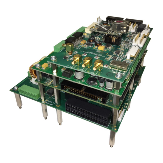
Introduction 1 INTRODUCTION The RC4600 Servo Antenna Control Unit (ACU) board set consists of a stackable set of cards allowing for compact and flexible ACU packaging. The design and function of the RC4600 ACU is a continuation of development based on the RC4000 line of mobile antenna control systems. -
Page 11: Manual Conventions
Latitude and longitude of the mount are presented in degree/minute (38°56 N) format. When referring to an RC4600 mode of operation, that mode’s name will be capitalized – ex. LOCATE. Throughout the RC4600 manual and software, the latitude, longitude and true heading of the mount are collectively referred to as the mount’s “position”. -
Page 12: Rc4600 Features
Chapter 1 Introduction 1.3 RC4600 Features The RC4600 performs its functions via digital and analog electronic equipment interfaced to the antenna’s motor drive and position sensor systems. This equipment is controlled through embedded software algorithms run by the RC4600’s microcontroller. -
Page 13: Hardware Overview
Introduction 1.4 Hardware Overview The following figure is a block diagram showing the four major components of the RC4600 board set and how they interface with a typical antenna system. Individual interfaces will be described in detail in Chapter 2. NOTE: Appendix C “Enclosure Specific... -
Page 14: Software Overview
The user selects which satellite to locate from the satellite database or by manually entering satellite data. The RC4600 checks that the calculated pointing solution is within the antenna’s range of movement and prompts the user to automatically position the antenna. -
Page 15: Automatic Antenna Stow
1.5.1.2.1 Configuration Screens Configuration mode screens allow the user to customize and calibrate the operation of the RC4600 for use with a particular antenna. Note that most configuration items will be factory set for correct operation with a particular antenna. -
Page 16: Graphical User Interface Overview
RC4600 ACU Board Set Chapter 1 Introduction 1.5.2 Graphical User Interface Overview The graphical user interface control option is available via the IP interface of the controller. It is designed to provide all the functions available from the front panel operation in an easy to use interface. As well as... -
Page 17: Specifications
RC4600 ACU Board Set Chapter 1 Introduction 1.6 Specifications RC4600 BOARDSET Physical Size 6 1/16" x 7" x 3 3/4" (with RCI plate and RF board) Weight 2.6 lbs. Default: 20 - 28 VDC Input Power Other options available Fusing... -
Page 18: Software
2 SOFTWARE 2.1 Operation Overview The RC4600 allows multiple options for mechanizing the user interface. These can be divided into 2 distinct groups. The first are versions that utilize a 4x4 keypad and 4x40 LCD display. Operation using this method will be described in section 0 and includes the following methods of control: •... -
Page 19: Front Panel Software Operation
2.1.1.1.1 Modes The functionality of the RC4600 is achieved by placing the controller in the desired mode of operation. The diagram below shows the hierarchy of the RC4600’s modes. Each mode has a unique display screen that presents the information applicable to that mode’s operation. -
Page 20: Keypad Usage
Introduction 2.1.1.1.2 Keypad Usage The keypad provides a flexible method of controlling the functionality of the RC4600. While each RC4600 mode has different requirements for user input, the use of the keypad remains consistent throughout all modes. The keypad provides for both specific actions and general data input. As an example, the <2/UP/N> key initiates an antenna up movement while in MANUAL mode but also allows for the entry of the number 2 when numeric entry is required or the indication of North when entering a latitude value. - Page 21 RC4600 ACU Board Set Chapter 1 Introduction KEY LABEL SPECIFIC FUNCTION GENERAL FUNCTION Momentary push switches between modes within group. Mode No specific function Button held for 5 seconds switches between operational and programming groups. Momentary push also exits sub-mode screens.
- Page 22 RC4600 ACU Board Set Chapter 1 Introduction KEY LABEL SPECIFIC FUNCTION GENERAL FUNCTION Move azimuth axis clockwise in Supplies “6” for numeric entry. Az CW MANUAL mode Supplies West for longitude entry. (123°45W) Requests move to predefined Supplies “7” for numeric entry.
-
Page 23: Data Entry
Introduction 2.1.1.1.3 Data Entry Many RC4600 screens request some type of user input. This section provides instructions on the entry of various types of data. Selection from List (<0-9>SELECT) When the user is prompted to select an action from a displayed list, pressing the numbered key corresponding to the desired action will initiate the action. -
Page 24: Display Layout
W A I T I N G T O R E P O S I T I O N . . . < 0 > - M E N U MODE TITLE: In the upper right corner the title of the current RC4600 mode is displayed – in this example TRACK designates that the RC4600 is currently in track mode. -
Page 25: Front Panel Operating Group
MENU mode allows the user to select the modes that implement the RC4600’s automatic movement features. While in either one of these modes, a momentary push of the Mode key will transition the RC4600 to the other mode. - Page 26 RC4600 ACU Board Set Chapter 1 Introduction The EL field shows a current position value of the elevation axis. It also shows the status of elevation limits (STOW, DOWN, UP). The limits will be displayed based on the table below. It is possible for different limits to have different sources (Switch Hardware for Up and Down software for stow).
-
Page 27: Heading Fix
RC4600 ACU Board Set Chapter 1 Introduction degrees clockwise will move the axis beyond the clockwise limit, the movement will be achieved by moving 90 degrees counter-clockwise. RF/EXT/BCN/DVB: This field shows the current signal strength sensed on the selected signal strength channel. By pressing the <Scroll Dn RF/SS>... - Page 28 NOTE: to make this “fixed heading” persist through the next powering down of the RC4600, the mount’s position would need to be “saved” via the POSITION mode. If the difference is applied, the RC4600 will proceed to the POSITION screen.
-
Page 29: Menu Mode
The sequence of axis movement will be mount dependent. Following completion of movement to the deploy position, the RC4600 will return to MANUAL mode. The automatic movement may be terminated anytime by pressing the <Stop> key. -
Page 30: Stow
- the azimuth axis is moved to its predefined stow position (typically az:0.000). After moving to this indicated position, the RC4600 will confirm the position by looking to see if the azimuth stow switch is active. If the azimuth stow switch is not recognized, the mount will be moved a short distance to either side of the current position trying to find the azimuth stow switch. -
Page 31: Locate
RC4600’s position has not been updated. If the lat/lon or heading data is not considered valid by the RC4600, asterisks will be displayed in the appropriate field and the “parameter needed” message will be triggered in the location readiness field. - Page 32 Chapter 1 Introduction If a valid lat/lon is received from the GPS then the lat/lon information will be displayed. Next the RC4600 will flash “MAGVAR” while it calculates the local magnetic deviation as a function of latitude, longitude and time. After calculating the local magnetic variation, the RC4600 will poll the compass for magnetic heading information.
-
Page 33: Satellite Selection
The appropriate message will be displayed to indicate that the RC4600 does not think it can move the antenna to the correct position to acquire the satellite. The user may have to move the antenna to place it in an orientation that will allow the mount to move to the required position. - Page 34 When locating a satellite, the RC4600 will use the information available in the satellite database to locate the selected satellite. The trees for selecting which satellite to use for a locate is shown in the flowchart on the following two pages.
- Page 35 RC4600 ACU Board Set Chapter 1 Introduction...
- Page 36 RC4600 ACU Board Set Chapter 1 Introduction...
-
Page 37: Locate Automatic Movement
This is so the polarization mechanism will be in the correct position to be able to detect received signal strength. Note: this selection is not requested if the feed type is defined as “circular”. In this case the RC4600 will immediately begin the locate automatic movement after ENTER is pressed from the main LOCATE screen. -
Page 38: Azimuth Scan
Note also that the Azimuth Scan movement may be truncated due to the limits of azimuth movement. 4) After completing the Azimuth Scan, the RC4600 will return the antenna to the “Center of Lock” or location of peak signal strength. -
Page 39: Peak Up
When this occurs, the RC4600 will have difficulty determining which satellite is the desired target. Following the completion of the Azimuth Scan, the RC4600 will immediately move to performing an azimuth and elevation peak up. 2.1.1.2.2.3.4 Peak Up The Peak Up routine will automatically begin at the end of an Azimuth Scan. -
Page 40: Box Peak
The Box Peak is a second peak operation that can be used to move the antenna from a first side-lobe and onto the main beam. If configured, the RC4600 will perform this operation immediately at the end of a Peak Up during all locates. -
Page 41: Spiral Search
Spiral Search will perform a search that is wide in azimuth and short in elevation. The term for this is a “Flat Spiral Search” 4) At the end of the Spiral Search, the RC4600 will perform a Peak Up (2.1.1.2.2.3.4) and a Box Peak (2.1.1.2.2.3.5). -
Page 42: Track
When the user chooses to manually enter the satellite data, a screen appears with fields to enter the three required pieces of data. Once a satellite is selected the RC4600 will display the screen below to prompt the user to verify that the antenna is currently peaked on target. - Page 43 The RC4600 will be constantly calculating pointing angles from the TLE data set. Anytime the current position is different from the calculated position, the RC4600 will move the antenna to close this error.
-
Page 44: Position
The first screen that appears shows the current mount position used in the RC4600. Also shown are the source that was used to acquire the current position data. If any field was not already populated, *** would be shown. -
Page 45: Heading
< M O D E > E X I T When option 3 is selected, the RC4600 will pull in the lat/lon from the GPS. Once complete the controller will automatically move back to the main POSITION screen. Note that if movement is required to acquire the GPS information, the following screen will be displayed so the user can confirm the movement. -
Page 46: Tilt
R O L L : 0 . 3 7 When option 3 is selected, the RC4600 will pull in the tilt from the dual axis inclinometer. Once complete the controller will automatically move back to the main POSITION screen. Note that if movement is required to acquire the pitch and roll information, the following screen will be displayed so the user can confirm the movement. -
Page 47: Moveto
The state of this field when this mode is entered will be “NORMAL”. This means that any move will be using the standard speed control of the RC4600. When the <0/Speed> key is pressed, this field will change to “SLOW”. This means that the move will never go faster than the slow speed set in the “DRIVE PARAMETERS”... -
Page 48: Peakup
RC4600 ACU Board Set Chapter 1 Introduction 2.1.1.2.2.8 PEAKUP The PEAKUP mode performs a quick peak on the signal source currently displayed on the top line of the display in MANUAL mode. This is the same routine that is used during the LOCATE operation... -
Page 49: Graphical User Interface Software Overview
Introduction 2.1.2 Graphical User Interface Software Overview The Graphical User Interface to the RC4600 can be accessed by navigating to the IP address of the controller using a web browser. The default IP address of the RC4600 is 192.168.1.1 2.1.2.1 Graphical User Interface Main Page The main page contains all important information about the current status of the RC4600 as well as the antenna. -
Page 50: Acu Status Window
2.1.2.1.1 ACU Status Window The ACU status window shows current information about the RC4600 and the last satellite located. Any alarms that are currently present will also display in the ACU status window box. In the image below, the standby alarm is displayed. Note that the box will also turn red when an alarm is present. -
Page 51: Alternate Position Displays
RC4600 ACU Board Set Chapter 1 Introduction 2.1.2.1.2.1 Alternate Position Displays By default, the GUI always displays the local horizontal azimuth, elevation and polarization angles. Additional readouts such as local platform angles, or true azimuth angles can be switched to by clicking on the label under each gauge. -
Page 52: Elevation
RC4600 ACU Board Set Chapter 1 Introduction 2.1.2.1.2.1.2 Elevation The table below shows each of the options for the elevation display. Local Horizontal Local Platform Platform Angle + Platform Angle Pitch/Roll... -
Page 53: Local Jog Control
RC4600 ACU Board Set Chapter 1 Introduction 2.1.2.1.3 Local Jog Control The bottom right side of the main page provides a keypad for manual jog control of the antenna. The keys provide the ability to jog the antenna in azimuth, elevation, and polarization. It also provides the ability to move to the preset H and V positions, as well as providing the ability to move the feed a preset 90°... -
Page 54: Main Display Window
The center section of the display is used to display the satellite arc of the current satellites in the satellite database (2.1.2.2.1). The preset satellites shown will be specific to the current band the RC4600 is configured to use. In the window above, the RC4600 is set for a Ka-Band feed. Since only three preset satellites are configured for Ka-Band, only 3 are shown. -
Page 55: Spectrum Analyzer Display
Introduction 2.1.2.1.4.2 Spectrum Analyzer Display If the RC4600 is equipped with the spectrum analyzer option, a button will be available on the left side of the main display that will allow you to switch to the spectrum analyzer display. The Spectrum Analyzer functional window consists of the spectrum display on the left side and spectrum analyzer controls on the right side. -
Page 56: Frequency Controls
RC4600 ACU Board Set Chapter 1 Introduction 2.1.2.1.4.2.1 Frequency Controls The Frequency control allows the Center Frequency and Span to be controlled. Both parameters may be incremented by using the + - keys. The Increment for Center frequency is 1/5th of one division. -
Page 57: Marker Controls
In the image above, the left box shows the current pointing angles in azimuth and elevation (yellow dot), and the track table points (red dots) and the path that the RC4600 will take between points. The box on the right shows a graphical representation of the last 2 minutes and 30 seconds of signal strength. -
Page 58: Automatic Operations
Introduction 2.1.2.1.5 Automatic Operations Down the left side of the display eight boxes that provide various automatic operations for the RC4600. Each of those functions are described in the corresponding section below. 2.1.2.1.5.1 Deploy The <Deploy> button automatically moves the antenna to the predefined “deploy”... -
Page 59: Locate
RC4600 ACU Board Set Chapter 1 Introduction 2.1.2.1.5.3 Locate The <Locate> button allows the user to enter the LOCATE mode (2.1.1.2.2.3). After clicking the <Locate> button, the user is presented with a list of preset satellites. The list of satellites is the set of satellites from the database that have the same band as the current feed. -
Page 60: Track
RC4600 ACU Board Set Chapter 1 Introduction 2.1.2.1.5.4 Track The <Track> button allows the user to enter the TRACK mode (2.1.1.2.2.4). After clicking the <Track> button, the user is presented with a list of preset satellites. The list of satellites is the set of satellites from the database that have the same band as the current feed. -
Page 61: Resume Track
RC4600 will position the antenna to the appropriate angles automatically. If there is not data for the current time, the RC4600 will perform a Peak Up (2.1.1.2.2.3.4) using the track source and then begin the track. -
Page 62: Move To
RC4600 ACU Board Set Chapter 1 Introduction 2.1.2.1.5.6 Move To The <Move To> button allows the user to move the antenna to a specified azimuth, elevation, and polarization angles. After clicking the <Move To> button, the user will be presented with a dialog box to enter azimuth, elevation, and polarization angles. -
Page 63: Position
The Heading dialog allows the user to select between <Use Compass> and <Enter Manually>. If the RC4600 already has a value for True and Magnetic, they will be shown. When set to <Use Compass>, the fields will be grayed out to show that they can’t be modified. When set to <Enter Manually>, the fields... -
Page 64: Tilt
2.1.2.1.5.7.3 Tilt The Tilt dialog allows the user to select between <Use Tilt Sensor> and <Enter Manually>. If the RC4600 already has a value for Pitch and Roll, they will be shown. When set to <Use Tilt Sensor>, the fields will be grayed out to show that they can’t be modified. -
Page 65: Signal Strength And Transmit Status
The indicator shown below indicates that the previous LOCATE finished successfully. This indicator will stay green until the RC4600 is powered off, or a new LOCATE is started. The indicator will be grayed out at the end of a LOCATE if it was unsuccessful. -
Page 66: Maintenance
RC4600 ACU Board Set Chapter 2 Hardware 2.1.2.1.7 Maintenance Clicking on the wrench and screwdriver in the upper right hand corner of the main page will open the dialog box below. This dialog box will allow you to access the remote front panel interface (2.1.1) -
Page 67: Configuration Page
The System Summary tab will provide you with the current software on the RC4600, as well as the serial number for the controller. At the bottom of the window is a <Return> button. Clicking this button will always return the user to the main page of the GUI (2.1.2.1). -
Page 68: Satellite Database
RC4600 ACU Board Set Chapter 2 Hardware 2.1.2.2.1 Satellite Database The Satellite Database tab gives the user to edit information about the preset list of 20 satellites. Each satellite entry can be expanded individually. The following screen shows an example full satellite database list. -
Page 69: Satellite Configuration
RC4600 ACU Board Set Chapter 2 Hardware 2.1.2.2.1.1 Satellite Configuration Clicking on a satellite in the database will expand the satellite to show additional field. All fields in the satellite preset are editable by typing on a keyboard. Additionally, the Two-Line Element data can be copied and pasted into the window. -
Page 70: System Settings
Hardware 2.1.2.2.2 System Settings The System Configuration tab allows the user to modify various information about the RC4600. 2.1.2.2.2.1 ACU Configuration The ACU configuration window allows the user to adjust information about the current feed that is being used. For systems that have the multi-feed sensing system, this window will not be available. In addition to the feed information, there may be additional antenna specific ACU configuration items available here. -
Page 71: Additional Ip Devices
RC4600 ACU Board Set Chapter 2 Hardware 2.1.2.2.2.3 Additional IP Devices If there are any other IP devices on the system that the ACU needs to communicate with (Spectrum Analyzer, Modem, etc.), an additional window will exist to notify the ACU of the IP parameters of that... -
Page 72: Advanced
Advanced The Advanced tab provides the user with the ability to upload and download configuration data from the RC4600. Additionally, the Advanced tab provides the user with the ability to load new firmware and user interface software onto the RC4600. -
Page 73: Configuration Data
The Configuration Data window allows the user to download a text file that contains all the configuration items contained in the RC4600. Additionally, by clicking <Choose File>, the user would be able to browse to a previously downloaded Configuration Data text file and load the configuration into the current RC4600. -
Page 74: Tle Data
The TLE Data window allows the user to TLE data from a text file. Any satellite in the database that has TLE data will have the NORAD catalog number associated with it. When a text file is loaded, the RC4600 will match the catalog number with the corresponding data in the config file and update the TLE data in the controller. -
Page 75: Acu Firmware
Hardware 2.1.2.2.3.4 ACU Firmware The ACU Firmware window allows the user to update the current software on the RC4600. Prior to updating the ACU Firmware, the configuration data from the controller should be downloaded via the Configuration Data window (2.1.2.2.3.2). -
Page 76: User Interface Firmware
The User Interface Firmware window allows the user to update the current user interface software on the RC4600. NOTE: Updating the user interface firmware may cause the IP settings of the RC4600 to be reset to factory defaults. The default IP address of the RC4600 is 192.168.1.1. -
Page 77: Support
RC4600 ACU Board Set Chapter 2 Hardware 3 SUPPORT 3.1 Troubleshooting 3.1.1 Warning Displays 3.1.1.1 General Warnings Alarm Description/Recommended Action Low Battery Battery used to backup NVRAM and Date/Time is low. Replace internal battery backup. Invalid Date/Time Date/Time is corrupt. Reset the Date/Time via maintenance or GPS time sync. -
Page 78: Polarization
RC4600 has sent a message to the GPS to start communication. GPS Offline RC4600 is not receiving information from the GPS receiver Waiting For GPS RC4600 is waiting for the GPS to report that it has a valid Lat/Lon 3.1.1.6 Compass Warning Description/Recommended Action... -
Page 79: Alarm Displays
RC4600 ACU Board Set Chapter 2 Hardware 3.1.2 Alarm Displays 3.1.2.1 General Alarms Alarm Description/Recommended Action Flash Version Mismatch Flash Memory Structure error. Reset defaults, recalibration of controller will be required. Flash Data Corrupt Items in Flash Memory are corrupt. Reset defaults, recalibration of controller will be required. -
Page 80: Polarization
RC4600 ACU Board Set Chapter 2 Hardware 3.1.2.4 Polarization Alarm Description/Recommended Action Drift Antenna was attempting to hold an azimuth position and the antenna drifted outside of the drift error configuration item range. Verify axis movement working as expected and that the drift error configuration item is set properly. -
Page 81: Acu Topics
Given the antenna’s latitude and longitude and the pointing vector to the satellite, the RC4600 calculates the elevation (with respect to local horizontal) required. Feedback from the antenna on the elevation axis... - Page 82 90 (135 – 45) degrees clockwise is therefore needed to point at the satellite. Since a position sensor on the azimuth axis is always active, the RC4600's default displayed azimuth value is that of the antenna angle. Derived estimates of the magnetic and true heading of the mount may...
-
Page 83: Polarization Control
The RC4600 allows the user to specify the type of polarization axis mechanism present. If a circular polarized feed is present, no automatic movement of the polarization axis is performed. If a linear polarized feed is present, the RC4600 will calculate the theoretical position as a function of the antenna position (latitude/longitude, heading, pitch/roll) and satellite longitude. - Page 84 RC4600 ACU Board Set Chapter 2 Hardware The following diagram shows a typical range of movement for mobile satellite antennas. Note that elevation movement to the stow position is limited about a small range of azimuth movement in order to ensure safe stowing of the antenna.
-
Page 85: Follow, Drift, And Drive Error Sensing
System time is maintained by the RC4600’s real time clock. The real-time clock is backed up by battery so that system time is available as soon as the RC4600 powers up. The system time is used to calculate sidereal time for maintaining track tables. Since satellite’s do not experience time shifts (such as from Standard Time to Daylight Savings Time or when moving from one time zone to another), it is recommended that system time not be modified while active track tables are present. -
Page 86: Magnetic Variation
In order to calculate satellite pointing solutions, the antenna’s orientation with respect to True North must be known. The RC4600 uses a compass to measure the local horizontal component of the earth’s magnetic field. The earth’s magnetic field is very irregular as shown in the following map. -
Page 87: System Performance
This feature is explained in full in section 2.1.1.2.2.3.3. The RC4600 uses 16-bit resolvers, or 25- bit optical encoders to sense azimuth and elevation position. The 16-bit sensors offer a resolution of 0.0055°, where the 25-bit optical encoders offer a resolution of...
Need help?
Do you have a question about the RC4600 and is the answer not in the manual?
Questions and answers