
Related Manuals for Kühtreiber MAKin 200 P HF AC/DC


Summary of Contents for Kühtreiber MAKin 200 P HF AC/DC
- Page 1 NÁVOD K OBSLUZE / SVAŘOVACÍ STROJ USER MANUAL / WELDING MACHINE MAKin 200 P HF AC|DC...
- Page 2 ČESKY doporučujeme svěřit údržbu a případné opravy naší servisní organizaci, která má dostupné příslušné vyba- vení a speciálně vyškolený personál. Veškeré naše stroje a zařízení jsou předmětem dlouhodobého vývoje. Proto OBSAH si vyhrazujeme právo na změnu během výroby. ÚVODNÍ INFORMACE A POPIS STROJE ....2 Popis NASTAVENÍ...
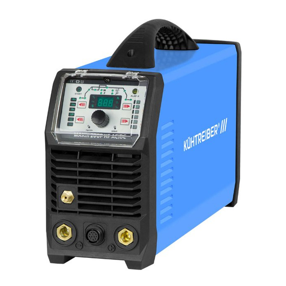
- Page 3 Popis hlavních částí stroje Přípojka svařovacího hořáku TIG / kabelu MMA (-) Přípojka ochranného plynu Ovládací panel Displej LED Ovládací n-kodér Přípojka zemnícího kabelu TIG / kabelu MMA (+) Konektor dálkového ovládání Síťový vypínač Přívod ochranného plynu 10 Přívodní kabel...
- Page 4 Přehled funkcí a jejich parametry TIG AC Předfuk plynu [ s ] 0 - 2 Startovací proud [ A ] UP SLOPE [ s ] 0 - 10 DOWN SLOPE [ s ] 0 - 10 Koncový proud [ A ] Dofuk plynu [ s ] 0 - 10...
- Page 5 Popis ovládacího panelu Pozice 1 Kontrolka zapnutí Pozice 2 Zobrazení funkcí TIG Pozice 3 Kontrolka přehřátí / chyb Pozice 4 Režim dvoutakt Pozice 5 Funkce CYCLE Pozice 6 Režim čtyřtakt Pozice 7 TIG DC Pozice 8 TIG AC - průběh kvadrát Pozice 9 TIG AC - průběh sinusoida Pozice 10...
- Page 6 Nastavení svařovacích parametrů Tlačítko přepínání metod TIG DC Nastavení metody svařování Výběr a potvrzení svařovací metody se provádí pomocí ovládacího tlačítka přepínání metod. MMA - metoda určena pro svařování obalovanou elek- trodou CrNi, Al, slitin a ocelových materiálů TIG HF - Metoda určena ke svařování CrNi a ocelových materiálů...
- Page 7 HOT START TIG AC - Nastavení průběhu AC Pomocí tlačítka přepínání průběhu zvolte vhodnou vari- antu. AC kvadrát - dochází k maximální penetraci materiálu, vy- soké postupové rychlosti a stabilnějšímu oblouku. AC sinusoida - standardní AC průběh, tišší oblouk a měkčí dynamika oblouku.
- Page 8 TIG AC - Nastavení funkce PRE-GAS TIG AC - Nastavení funkce UP SLOPE (předfuk plynu) (plynulý náběh) Funkce slouží k zajištění ochranné atmosféry před zapá- Funkce umožňuje nastavení plynulého nárůstu proudu lením svařovacího oblouku. Stisknutím ovládacího tla- z funkce START CURRENT na hlavní svařovací proud. Vli- čítka na hořáku dojde k aktivaci funkce, která...
- Page 9 tak, aby nedocházelo k přílišnému zahřívání wolframové TIG AC - Nastavení funkce END CURRENT elektrody a následné tvorbě kuličky na jejím konci. Ná- (koncový proud) sledkem vytvoření kuličky dochází k nestabilnímu hoření Funkce udává hodnotu proudu, při které dojde k ukon- svařovacího oblouku a ztráty možnosti řízení...
- Page 10 TIG AC - Nastavení funkce 2-TAKT TIG AC - Nastavení funkce PULSE Funkce udává způsob aktivace svařovacího procesu. Při (dolní proud) použití tohoto režimu je nutné v průběhu svařování mít Nastavením hodnoty dochází k určení dolního svařo- stisknuté ovládací tlačítko, které zasílá signál k aktivaci vacího proudu I pulzu.
- Page 11 TIG HF AC kvadrát AC sinusoida AC kvadrát AC sinusoida Tlačítko Ovládací n-kodér Tlačítko přepínání TIG HF Ovládací n-kodér Tlačítko přepínání průběhů přepínání režimů průběhů TIG AC - Nastavení druhého proudu TIG AC - Vypnutí funkce funkce CYCLE PULSE / SPOT WELDING Aktivace se provádí...
- Page 12 TIG DC - Nastavení svařovacího proudu Nastavení svařovacího proudu se provádí otáčením ovlá- dacího n-kodéru. Aktivace se provádí postupným stisknu- tím ovládacího n-kodéru. TIG HF Kontrolka hl. proudu Svařovací proud TIG HF Ovládací n-kodér Tlačítko přepínání průběhů TIG DC - Nastavení funkce UP SLOPE (plynulý...
- Page 13 TIG HF Ovládací n-kodér Tlačítko přepínání průběhů TIG HF Ovládací n-kodér Tlačítko přepínání průběhů TIG DC - Nastavení funkce END CURRENT TIG DC - Nastavení funkce 2-TAKT (koncový proud) Funkce udává způsob aktivace svařovacího procesu. Při Funkce udává hodnotu proudu, při které dojde k ukon- použití...
- Page 14 TIG HF TIG HF Ovládací n-kodér Tlačítko přepínání průběhů Tlačítko Ovládací n-kodér Tlačítko přepínání přepínání režimů průběhů TIG DC - Nastavení funkce PULSE (dolní proud) TIG DC - Nastavení funkce Nastavením hodnoty dochází k určení dolního svařova- FREQUENCY PULSE (frekvence pulzu) cího proudu I pulzu.
- Page 15 TIG HF SPOT - Nastavení funkce SPOT WELDING (bodové svařování) Tato funkce je určena k bodovému svařování ocelových a nerezových materiálů. Pomocí automatického ukončení svařovacího oblouku je zajištěno kvalitní spojení. Uživatel musí nastavit dostatečný čas a výkon pro zajištění ideál- ního spojení.
- Page 16 SPOT - Nastavení funkce DUTY CYCLE (balanc proudů) Funkce umožňuje nastavení poměru mezi hlavním sva- řovacím proudem a pulzním proudem I . Snižováním hodnoty pulzního proudu dochází ke snížení tepelného zatížení a penetrace svařovaného materiálu. TIG HF TIG HF Ovládací n-kodér Tlačítko přepínání průběhů JOB Mode Funkce umožňuje ukládání...
- Page 17 Svařování metodou TIG Nahrání uživatelského programu Stiskněte ovládací n-kodér na cca 2 s. Na displeji vyber- 1. Připojte svařovací příslušenství. Svařovací hořák na te volbu „L“ a potvrďte stisknutím ovládacího n-kodéru. pól (-), zemnící kabel na pól (+), připojte ochranný Následně...
- Page 18 0 - 5 s POST GAS START 1-3 mm 8-10 mm 1-3 mm 1-3 mm průběh svařovacího procesu u TIG LA Obr. 2 - 5. Zakončení svařovacího procesu a aktivace DOWN Obrázek 3 SLOPE (vyplnění kráteru) se provádí oddálením wolframové elektrody na cca 8 - 10 mm od svařova- α...
- Page 19 Ochranný plyn: Tabulka 4 Pro svařování metodou TIG je nutné použít Argon o čisto- s (mm) a (mm) d (mm) α (°) tě 99,99 %. Množství průtoku určete dle tabulky 3. 0 - 3 Tabulka 3 0,5 (max) Svařovací Průměr Průtok 4 - 6 1 - 1,5...
- Page 20 Tabulka 5 Tabulka 7 Síla svařovaného Průměr elektrody s (mm) a (mm) d (mm) α (°) materiálu (mm) (mm) 0 - 3 1,5 - 3 3 - 6 s/2 (max) 3 - 5 3 - 12 0 - 1,5 0 - 2 5 - 12 3,25 >...
- Page 21 Chybová hlášení Chyba Příčina Řešení Kontrolka zapnutí je poškozena, Vyměňte kontrolku, zkontrolujte Po zapnutí stroje nesvítí kontrolka chybně zapojena. okruh zapojení. zapnutí, ventilátor funguje. Výkonová PCB je poškozena. Opravte / vyměňte výkonovou PCB. Ventilátor je blokován cizím tělesem. Odstraňte těleso. Po zapnutí...
-
Page 22: Table Of Contents
ENGLISH maintenance and repair work to our service organizati- on, which has the appropriate equipment and specially trained personnel. All our machines and equipment are subject to long-term development. Therefore, we CONTENT reserve the right to make changes during production. INTRODUCTION AND MACHINE DESCRIPTION ... - Page 23 Description of the main parts of the machine TIG welding torch / MMA cable connection (-) Protective gas connection Control panel LED display Control n-coder TIG / MMA (+) Grounding Cable Connection Remote control connector Power switch Protective gas supply 10 Power cord | 23...
- Page 24 Overview of features and their parameters TIG AC PRE GAS [ s ] 0 - 2 Starting current [ A ] UP SLOPE [ s ] 0 - 10 DOWN SLOPE [ s ] 0 - 10 End Current [ A ] POST GAS [ s ] 0 - 10...
- Page 25 Description of the control panel Position 1 Power-on lamp Position 2 Display of TIG functions Position 3 Overheat / fault indicator Position 4 Two stroke mode Position 5 CYCLE function Position 6 Four stroke mode Position 7 TIG DC Position 8 TIG AC - square waveform Position 9 TIG AC - sinusoid waveform...
-
Page 26: Setting The Welding Parameters
Setting of welding parameters Method switching button TIG DC Setting the welding method The selection and confirmation of the welding method is done using the method switch control button. MMA - method for welding with coated electrode CrNi, Al, alloys and steel materials TIG HF - The method is designed for welding of CrNi and steel materials with DC current and Al materials with AC current. - Page 27 HOT START TIG AC - Setting the AC waveform Use the waveform switch to select the appropriate option. AC square - maximum penetration of material, high pro- gressive speed and more stable arc. AC sinusoid - standard AC waveform, quieter arc and sof- ter dynamics of the arc.
- Page 28 TIG AC - Setting PRE-GAS function TIG AC - Setting UP SLOPE function (gas pre-flow) (smooth start) The function serves to provide a protective atmosphere The function allows to set a continuous increase of cu- against ignition welding arc. Pressing the control button rrent from the START CURRENT function to the main on the burner activates the function that is active for welding current.
- Page 29 electrode does not overheat and the ball is formed at its TIG AC - Setting END CURRENT function end. As a result of the formation of a ball, the welding arc (end current) becomes unstable and the possibility of controlling the The function indicates the current value at which the arc direction is lost.
- Page 30 TIG AC - Setting 2-STROKE function TIG AC - Setting PULSE function The function indicates how the welding process is acti- (lower current) vated. When using this mode, it is necessary to press the Setting the value determines the lower welding current control button during welding, which sends a signal to of the pulse.
- Page 31 TIG HF AC - square AC - sinusoid TIG AC - Second current setting - CYCLE function Activation is performed by pressing the control n-enco- der one after the other. AC - square AC - sinusoid Method switching N-coder Waveform switching button button TIG AC...
- Page 32 TIG DC - Welding current setting The welding current is set using the control n-coder. Acti- vation is performed by pressing the control n-encoder one after the other. TIG HF Main current indicator Welding current TIG HF N-coder Waveform switching button TIG DC - Setting UP SLOPE function...
- Page 33 TIG HF N-coder Waveform switching TIG HF N-coder Waveform switching button button TIG DC - Setting 2-STROKE function TIG DC - Setting END CURRENT function The function indicates how the welding process is acti- (end current) vated. When using this mode, it is necessary to press the The function indicates the current value at which the control button during welding, which sends a signal to welding process ends.
- Page 34 TIG HF TIG HF N-coder Waveform switching Mode switch N-coder Waveform switching button button button TIG DC - Setting PULSE function TIG DC - Setting FREQUENCE PULSE func- Setting the value determines the lower welding current I tion of the pulse. Activating this function reduces the thermal The function allows setting the frequency of the main load on the welded material.
- Page 35 TIG HF SPOT - Setting the SPOT WELDING func- tion This function is intended for spot welding of steel and stainless materials. The automatic welding arc terminati- on ensures a high-quality connection. The user must set sufficient time and power to ensure an ideal connection. This function is only active in TIG DC HF mode.
- Page 36 SPOT - Setting DUTY CYCLE function (current balance) The function allows you to set the ratio between the main welding current and the pulse current I . By decrea- sing the pulse current value, the heat load of the welded material and its penetration is reduced.
- Page 37 Welding in method TIG Uploading the user program Press the n-coder for about 2 seconds. Select “L” on the 1. Connect the welding accessories. Welding torch on display and press the n-coder to confirm. Then select the the pole (-), grounding cable on the pole (+), connect recording position (1-10) and press the n-coder to con- the protective gas.
- Page 38 0 - 5 s POST GAS START 1-3 mm 8-10 mm 1-3 mm 1-3 mm Picture 2 - welding process at TIG LA 6. Re-approach - Welding current decreases after the set Table 2 time to the end value set current (eg 10 A) - filling the α...
- Page 39 Protective gas: Table 4 For TIG welding, it is necessary to use argon with a puri- s (mm) a (mm) d (mm) α (°) ty of 99.99%. Determine the amount of flow according 0 - 3 to Table 3. 0.5 (max) Table 3 4 - 6 1 - 1.5...
- Page 40 Table 5 Table 7 Thickness of welded Diameter of the s (mm) a (mm) d (mm) α (°) material (mm) Electrode 0 - 3 1.5 - 3 3 - 6 s/2 (max) 3 - 5 3 - 12 0 - 1.5 0 - 2 5 - 12 3.25...
- Page 41 Error messages Error Cause Solution/Remedy The power-on lamp is damaged, Replace the indicator lamp, check When the machine is turned on, incorrectly connected. the wiring circuit. the power-on lamp is off, the fan is working. The power PCB is damaged. Repair / replace the power PCB.
-
Page 42: List Of Spare Parts
Seznam náhradních dílů / List of spare parts 42 |... - Page 43 Popis Description Rukojeť Handling handle Kryt Cover Zadní čelo Rear forehead Hlavní vypínač Main switch Průchodka kabelu Cable grommet Plynový ventil Gas valve Držák ventilátoru Fan holder Kryt ventilátoru Fan cover Ventilátor Bottom Řídící PCB Control PCB Hlavní transformátor Main transformer Tlumivka Choke Přední...
-
Page 44: Production Plate
Výrobní štítek / Production plate MAKin 200 P HF AC DC Popis Description Napájecí napětí Supply voltage Svařovací metoda Welding method Svařovací stroj Welding machine Typ stroje Machine type Jméno a adresa výrobce Name and address of manufacturer Výrobní číslo Serial number Normy Standards... -
Page 45: Electrical Scheme
Elektrotechnické schéma / Electrical scheme | 45... -
Page 46: Warranty Card
Osvědčení o jakosti a kompletnosti výrobku / Testing certificate Název a typ výrobku / Type MAKin 200 P HF AC|DC Výrobní číslo stroje Serial number Výrobce Producer Razítko OTK Stamp of Technical Control Department Datum Date of production Kontroloval Inspected by Záruční... - Page 47 | 47...
- Page 48 Výrobce si vyhrazuje právo na změnu. The producer reserves the right to modification. 04/2020 48 |...
Need help?
Do you have a question about the MAKin 200 P HF AC/DC and is the answer not in the manual?
Questions and answers