
Related Manuals for Extreme Networks ExtremeWireless AP560h


Summary of Contents for Extreme Networks ExtremeWireless AP560h
- Page 1 ExtremeWireless™ AP560h Access Point Installation Guide 9036166-01 Rev AA August 2020...
- Page 2 Copyright © 2020 Extreme Networks, Inc. All rights reserved. Legal Notice Extreme Networks, Inc. reserves the right to make changes in specifications and other information contained in this document and its website without prior notice. The reader should in all cases consult representatives of Extreme Networks to determine whether any such changes have been made.
-
Page 3: Table Of Contents
Table of Contents Preface......................................v Conventions..................................v Text Conventions..............................v Documentation and Training..........................vi Training..................................vi Getting Help................................... vi Subscribing to Service Notifications......................vii Providing Feedback to Us............................vii AP560h Overview........................ 8 AP560h Features................................8 Purchase Order Information..........................10 AP560h purchase order information....................... 10 Install the Access Point......................13 Verify the AP560h Box Contents........................13 Access Point Bracket Usage and Mounting Options................ - Page 4 Table of Contents FCC Declaration of Conformity Statement....................36 FCC Caution:............................... 36 Federal Communications Commission (FCC) Notice................37 Industry Canada (IC) Notice..........................38 Industry Canada (IC) Notice........................38 European Waste Electrical and Electronic Equipment (WEEE) Notice..........38 Index............................40 ExtremeWireless™ AP560h Access Point...
-
Page 5: Preface
Preface This section discusses the conventions used in this guide, ways to provide feedback, additional help, and other Extreme Networks® publications. Conventions This section discusses the conventions used in this guide. Text Conventions The following tables list text conventions that are used throughout this guide. -
Page 6: Documentation And Training
Training Extreme Networks offers product training courses, both online and in person, as well as specialized certifications. For more information, visit www.extremenetworks.com/education/. Getting Help If you require assistance, contact Extreme Networks using one of the following methods:... -
Page 7: Subscribing To Service Notifications
4. Click Submit. Providing Feedback to Us Quality is our first concern at Extreme Networks, and we have made every effort to ensure the accuracy and completeness of this document. We are always striving to improve our documentation and help... -
Page 8: Ap560H Overview
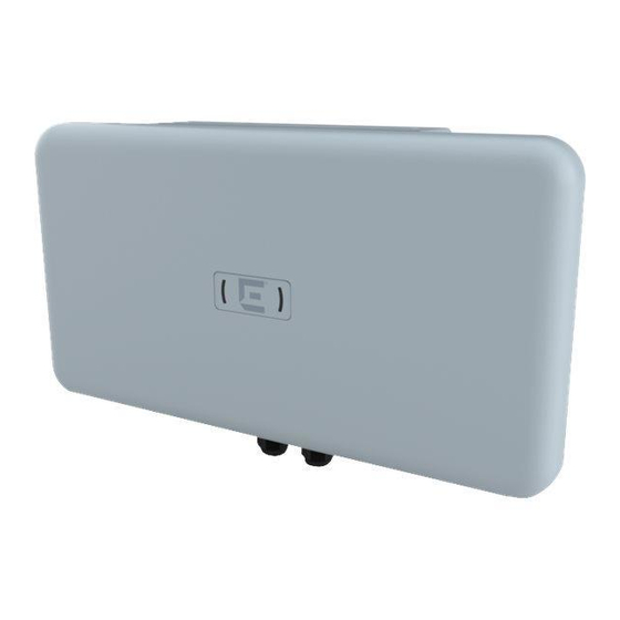
AP560h Overview AP560h Features on page 8 Purchase Order Information on page 10 The AP560h is a Wi-Fi 6, 802.11ax/ac/abgn outdoor access point. The access point caters to the stadium environment by supporting high density of users and devices. It offers flexible deployment options and can be mounted to a pole, and to a wall, thereby ensuring exceptional mobile experience throughout the stadium. - Page 9 AP560h Overview AP560h Features • Temperature: ◦ Operating temperature: -40°C to +55°C (-40°F to +131°F) ◦ Storage temperature: -40°C to +70°C (-40°F to +158°F) • Enclosure: Plastic only Figure 1: AP560h front view ExtremeWireless™ AP560h Access Point...
-
Page 10: Purchase Order Information
Purchase Order Information AP560h Overview Figure 2: AP560h access point side ports Callout Description GE1 port GE2 port Console port Note The console port cap must be tightened to a torque of 12 in-lbs. If a torque wrench is not available, a flat-bladed screwdrive can be used. The flat blade must be 7/16 in. - Page 11 AP560h Overview AP560h purchase order information You can install the access point to a wall or a pole using the KT-147407-02 bracket parts or the MBO- ART02, 10 in. 2-axis articulating mounting bracket, or the WS-MBO-POLE01 (#30520) bracket. The ordering details are described in the following tables. Table 3: KT-147407-02 bracket order information Part number Box contents...
- Page 12 AP560h purchase order information AP560h Overview The contents of the KT-150173-01 extension arm are described in the following table. Table 4: KT-150173-01 extension arm order information Part number Box contents KT-150173-01 One KT-150173-01 12 in. extension arm Two hex-head M12 stainless-steel screws Two hex-head M12 stainless-steel nuts One URL card Note...
-
Page 13: Install The Access Point
When you receive the access point bundle, perform a visual inspection of the access point, the bracket, and the accessories for any physical damage. Contact Extreme Networks Support in case of any damage. Before installing the access point: Procedure Verify the box contents. -
Page 14: Access Point Bracket Usage And Mounting Options
Access Point Bracket Usage and Mounting Options Install the Access Point Procedure 1. If you have ordered the AP560h access point separately, verify that the box contains the following items: Quantity Item AP560h Quick Reference AP560h access point 2. If you have ordered the service panel separately (EIO-03-SP), verify that the box contains the following items: Quantity Item... -
Page 15: Install The Access Point On A Wall
Install the Access Point Install the Access Point on a Wall Table 7: AP560h mounting brackets and accessories usage (continued) Mounting bracket/ Wall install Pole install Notes accessory and part number WS-MBO-POLE01 If the pole diameter is (#30520); bracket; also <= 1.0 in. -
Page 16: Install The Access Point Using Mbo-Art02 Articulating Mounting Bracket
Install the Access Point Using MBO-ART02 Articulating Mounting Bracket Install the Access Point • KT-150173-01 extension arm (see Figure 7 on page 21). • Six M6 screws • Four M6 size hex-head screws • Screw-in anchors if the access point is being mounted on a wood wall or a concrete surface. Note The M6 hex-head screws and screw-in anchors must be provided by the installer. - Page 17 Install the Access Point Using MBO-ART02 Articulating Install the Access Point Mounting Bracket Procedure 1. Using the MBO-ART02 articulating mounting bracket’s shorter bracket end as a template, mark and drill four holes on the wall. Figure 3: MBO-ART02 bracket template for attachment holes ExtremeWireless™...
- Page 18 Install the Access Point Using MBO-ART02 Articulating Mounting Bracket Install the Access Point 2. Attach the MBO-ART02 to the access point using two M6 hex-head screws. Use the mounting holes shown in Figure 4 to mount the MBO-ART02 bracket onto the AP560h access point.
-
Page 19: Install The Access Point On A Wall Or Flat Surface Using The Kt-147407-02 Bracket Parts
Install the Access Point on a Wall or Flat Surface Using Install the Access Point the KT-147407-02 Bracket Parts Install the Access Point on a Wall or Flat Surface Using the KT-147407-02 Bracket Parts Before You Begin Hardware requirements for a wall or flat surface installation: •... - Page 20 Install the Access Point on a Wall or Flat Surface Using the KT-147407-02 Bracket Parts Install the Access Point Figure 6: 1-axis tilt bracket Procedure 1. Attach the flat part of the KT-147407-02 bracket to the access point using two M6 screws. 2.
-
Page 21: Install The Access Point Using Kt-147407-02 Bracket Parts And Kt-150173-01 Extension Arm
Install the Access Point Using KT-147407-02 Bracket Install the Access Point Parts and KT-150173-01 Extension Arm Install the Access Point Using KT-147407-02 Bracket Parts and KT-150173-01 Extension Arm Before You Begin The hardware required for installation: • Flat part of the KT-147407-02 bracket •... -
Page 22: Install The Access Point Using Kt-150173-01 Extension Arm
Install the Access Point Using KT-150173-01 Extension Install the Access Point 4. Attach one end of the KT-150173-01 extension arm to the 1-axis tilt bracket using two hex-head M12 stainless-steel screws and two hex-head M12 stainless-steel nuts through the two large circular holes on the KT-150173- 01 extension arm. -
Page 23: Install The Access Point On A Pole Using Mbo-Art02 Articulating Mounting Bracket And Pole01 Bracket
Install the Access Point on a Pole Using MBO-ART02 Install the Access Point Articulating Mounting Bracket and POLE01 Bracket • Two M12 screws • Two M12 hex nuts • 0.5 in. wide stainless-steel cable clamps • KT-150173-01 extension arm Note You must provide M6 hex-head screws and screw-in anchors. - Page 24 Install the Access Point on a Pole Using MBO-ART02 Articulating Mounting Bracket and POLE01 Bracket Install the Access Point 2. Attach the WS-MBO-POLE01 bracket to the MBO-ART02 articulating mounting bracket using four M3 screws, nuts, and washers. ExtremeWireless™ AP560h Access Point...
- Page 25 Install the Access Point on a Pole Using MBO-ART02 Install the Access Point Articulating Mounting Bracket and POLE01 Bracket 3. Attach both the cable clamps to the WS-MBO-POLE01 bracket. Open the cable clamp by turning a flat bladed screwdriver counterclockwise. Then insert the non- clamp end into the pole bracket through the holes.
-
Page 26: Install The Access Point On A Pole Using Kt-147407-02 Bracket Parts
Install the Access Point on a Pole Using KT-147407-02 Bracket Parts Install the Access Point 5. Tighten the cable clamp screw clockwise, tightening the band around the pole. Figure 9: Tightening the cable clamps on the POLE01 bracket Install the Access Point on a Pole Using KT-147407-02 Bracket Parts Before You Begin The following hardware is required for pole installation using KT-147407-02 bracket parts: •... - Page 27 Install the Access Point on a Pole Using KT-147407-02 Install the Access Point Bracket Parts Figure 10: Pole part of the KT-147407-02 bracket Procedure 1. Attach the KT-147407-02 flat part and 1-axis tilt part to the access point. For instructions on how to attach the bracket parts, see Install the flat part and the 1-axis tilt part of the KT-147407-02 bracket to the access point.
-
Page 28: Install The Access Point On A Pole Using Kt-147407-02 Bracket Parts And Kt-150173-01 Extension Arm
Install the Access Point on a Pole Using KT-147407-02 Bracket Parts and KT-150173-01 Extension Arm Install the Access Point 2. Attach the KT-147407-02 pole part to the 1-axis tilt bracket using two M12 bolts through the large bracket holes on the 1-axis tilt bracket and the pole bracket. 3. - Page 29 Install the Access Point on a Pole Using KT-147407-02 Install the Access Point Bracket Parts and KT-150173-01 Extension Arm Mount the Access Point to a Pole using the Pole Part of the KT-147407-02 Bracket Before You Begin The following hardware is required for pole installation using KT-147407-02 pole bracket part to the access point: •...
-
Page 30: Ge1 Or Ge2 Cable Connection
GE1 or GE2 Cable Connection Before You Begin Connect the GE1 or GE2 cable before you install the plastic service panels. About This Task The GE1 or GE2 cable is connected through the service panel base front or rear hole. The following hardware is required to connect the GE1 or GE2 cable through the service panel base rear hole: •... - Page 31 GE1 or GE2 Cable Connection 6. Remove the GE1 port gland cap, plastic cage, and gasket. 7. Connect the GE1 cable through the GE1 gland port until it clicks into place. If there is a GE2 connection, insert the cable through the GE2 gland port until it locks into place. 8.
-
Page 32: Install The Plastic Service Panels On The Access Point
Install the Plastic Service Panels on the Access Point About This Task Use the plastic service panels when the MBO-ART02 articulating mounting bracket tilt is more than 20 degrees. Procedure 1. Attach the plastic service panel base to the access point using four, 75 mm service panel shoulder screws. - Page 33 Install the Plastic Service Panels on the Access Point 2. Torque the screws to 13 in-lbs. Figure 13: Plastic service panel base attachment holes on AP560h access point Callout Description Plastic service panel base attachment holes on AP560h access point 3.
-
Page 34: Product Specifications
Product Specifications Table 10: Physical specifications Item Description Dimensions 11.3 in. × 18.9 in. × 3.5 in. (288 mm × 481 mm × 88 mm) Housing 10.5lbs (4.77 kg) IP rating IP67 Console port RJ45 USB port USB 3.0 port, Type A for purpose built modules PoE failover Redundant PoE capable Anti-theft locks... -
Page 35: Regulatory And Compliance Information
Regulatory and Compliance Information Professional Installation Instruction on page 35 Safety Guidelines on page 36 FCC Declaration of Conformity Statement on page 36 Federal Communications Commission (FCC) Notice on page 37 Industry Canada (IC) Notice on page 38 European Waste Electrical and Electronic Equipment (WEEE) Notice on page 38 Professional Installation Instruction Installation personnel... -
Page 36: Instructions D'installation Professionnelle
Instructions d'installation professionnelle Regulatory and Compliance Information Instructions d'installation professionnelle Installation Ce produit est destine a un usage specifique et doit etre installe par un personnel qualifie maitrisant les radiofrequences et les regles s'y rapportant. L'installation et les reglages ne doivent pas etre modifies par l'utilisateur final. -
Page 37: Federal Communications Commission (Fcc) Notice
Regulatory and Compliance Information FCC Caution: reception, which can be determined by turning the equipment off and on, the user is encouraged to try to correct the interference by one of the following measures: • Reorient or relocate the receiving antenna. •... -
Page 38: Industry Canada (Ic) Notice
Industry Canada (IC) Notice Regulatory and Compliance Information This device is restricted to indoor usage only. Warning FCC Radiation Exposure Statement: This equipment complies with FCC radiation exposure limits set forth for an uncontrolled environment. This equipment should be installed and operated with a minimum distance of 26 cm between the radiator and your body. - Page 39 European Waste Electrical and Electronic Equipment Regulatory and Compliance Information (WEEE) Notice In accordance with Directive 2012/19/EU of the European Parliament on waste electrical and electronic equipment (WEEE): 1. The symbol above indicates that separate collection of electrical and electronic equipment is required.
-
Page 40: Index
Index AP560h features 8 pole installation ART02 on POLE01 bracket 23 KT-147407-02 bracket parts 26 pole installation using KT-150173-01 extension arm 28 Box Contents product specifications AP560h box contents 13 AP560h specifications 34 environmental specifications 34 physical specifications 34 power specifications 34 cable configuration GE1 cable configuration 30 GE2 cable configuration 30 conventions safety guidelines 36 notice icons v...
Need help?
Do you have a question about the ExtremeWireless AP560h and is the answer not in the manual?
Questions and answers