
Related Manuals for Extreme Networks ExtremeWireless AP560i


Summary of Contents for Extreme Networks ExtremeWireless AP560i
- Page 1 ExtremeWireless™ AP560i Access Point Installation Guide 9036165-01 Rev AA August 2020...
- Page 2 Copyright © 2020 Extreme Networks, Inc. All rights reserved. Legal Notice Extreme Networks, Inc. reserves the right to make changes in specifications and other information contained in this document and its website without prior notice. The reader should in all cases consult representatives of Extreme Networks to determine whether any such changes have been made.
-
Page 3: Table Of Contents
Table of Contents Preface......................................v Conventions..................................v Text Conventions..............................v Providing Feedback to Us............................vi Getting Help................................... vi Subscribing to Service Notifications......................vii Documentation and Training..........................vii Training................................... vii AP560i Overview......................... 8 AP560i Features................................8 AP560i Purchase Order Information........................11 AP560i order information..........................11 EIO-04 under-seat enclosure order information................. - Page 4 Table of Contents Safety Guidelines...............................44 FCC Declaration of Conformity Statement....................44 FCC Caution:............................... 44 FCC Radiation Exposure Statement.........................45 European Waste Electrical and Electronic Equipment (WEEE) Notice......... 45 Index............................46 ExtremeWireless™ AP560i Access Point...
-
Page 5: Preface
Preface This section discusses the conventions used in this guide, ways to provide feedback, additional help, and other Extreme Networks® publications. Conventions This section discusses the conventions used in this guide. Text Conventions The following tables list text conventions that are used throughout this guide. -
Page 6: Providing Feedback To Us
Italics are also used when referring to publication titles. Providing Feedback to Us Quality is our first concern at Extreme Networks, and we have made every effort to ensure the accuracy and completeness of this document. We are always striving to improve our documentation and help... -
Page 7: Subscribing To Service Notifications
Hardware/Software Compatibility Matrices https://www.extremenetworks.com/support/compatibility-matrices/ White papers, data sheets, case studies, https://www.extremenetworks.com/resources/ and other product resources Training Extreme Networks offers product training courses, both online and in person, as well as specialized certifications. For more information, visit www.extremenetworks.com/education/. ExtremeWireless™ AP560i Access Point... -
Page 8: Ap560I Overview
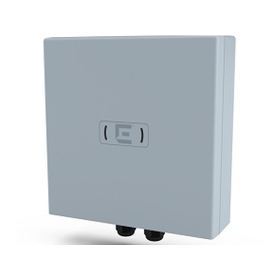
AP560i Overview AP560i Features on page 8 AP560i Purchase Order Information on page 11 The AP560i access point is a cloud-ready, stadium-optimized Wi-Fi 6, and 802.11ax/ac/ abgn outdoor access point with internal antenna. The AP560i access point caters to the stadium and outdoor environment by supporting high density of users and devices. - Page 9 AP560i Overview AP560i Features ◦ Storage temperature: -40°F to +158°F (-40°C to +70°C) • Enclosure: Plastic only Figure 1: AP560i side ports ExtremeWireless™ AP560i Access Point...
- Page 10 AP560i Features AP560i Overview Callout Description GE1 port GE2 port Console port Note The console port cap must be tightened to a torque of 12 in-lbs. If a torque wrench is not available, a flat-bladed screwdrive can be used. The flat blade must be 7/16 in.
-
Page 11: Ap560I Purchase Order Information
AP560i Overview AP560i Purchase Order Information AP560i Purchase Order Information The AP560i access point is sold by itself, and you need to order the mounting brackets and accessories separately for under seat, wall, or pole installations. AP560i order information Part number Description AP560i-FCC Cloud-ready, dual 5GHz, dual-band, sensor radio,... - Page 12 EIO-04 under-seat enclosure order information AP560i Overview EIO-04 under-seat enclosure order information Part number Box contents EIO-04 • EIO-04 Quick Reference Guide • Metal sloping bracket • Metal "L" brackets • Plastic service panel base • Plastic service panel top with one captive screw •...
- Page 13 AP560i Overview EIO-04 under-seat enclosure order information You can install the access point to a wall or a pole using the KT-147407-02 bracket parts or the MBO- ART02, 10 in. 2-axis articulating mounting bracket, or the WS-MBO-POLE01 (#30520) bracket. The ordering details are described in the following tables.
- Page 14 EIO-04 under-seat enclosure order information AP560i Overview The contents of the KT-150173-01 extension arm are described in the following table. Table 5: KT-150173-01 extension arm order information Part number Box contents KT-150173-01 One KT-150173-01 12 in. extension arm Two hex-head M12 stainless-steel screws Two hex-head M12 stainless-steel nuts One URL card Note...
-
Page 15: Install The Access Point
2. Visually inspect the access point, the bracket, and any other optional accessories you have ordered for physical damage. If there is any damage, contact Extreme Networks Support. 3. Review the safety guidelines. ExtremeWireless™ AP560i Access Point... -
Page 16: Access Point Bracket Usage And Mounting Options
Access Point Bracket Usage and Mounting Options Install the Access Point Access Point Bracket Usage and Mounting Options The AP560i access point can be mounted under a seat, on a wall, or to a pole, which are described in the following table. Table 8: AP560i mounting bracket usage Mounting bracket Wall install... - Page 17 Install the Access Point Access Point Bracket Usage and Mounting Options Table 8: AP560i mounting bracket usage (continued) Mounting bracket Wall install Pole install Under-seat install Notes and part number MBO-ART02 The articulating mounting bracket is paired with the POLE01 bracket for pole installations.
-
Page 18: Install The Access Point Under-Seat
Install the Access Point Under-Seat Install the Access Point Related Topics AP560i Purchase Order Information on page 11 Install the Access Point Under-Seat About This Task The AP560i is used with the EIO-03 or EIO-04 mounting kit during the under-seat installation procedure. - Page 19 Install the EIO-04 Under-Seat Enclosure and the Access Install the Access Point Point on a Slope 3. Place the metal sloping bracket, attach the nuts and washers to the exposed threads, and torque them to 60 in-lbs. About This Task Attach the conduit cable through the conduit holes on the metal sloping bracket, then attach the metal L bracket to the access point, and install the access point on a slope.
-
Page 20: Install The Eio-04 Under-Seat Enclosure With The Access Point On A Flat Surface
Install the EIO-04 Under-Seat Enclosure with the Access Point on a Flat Surface Install the Access Point 7. Run the cable through the conduit and add the RJ45 connectors to the wires. Note The cable must have 1 in. bend radius and be accessible to the glands on AP560i access point. -
Page 21: Install The Access Point On A Wall
Install the Access Point Install the Access Point on a Wall 6. Torque the nuts to 60 in-lbs. Figure 3: AP560i flat surface installation with metal “L” brackets What to Do Next Install the Plastic Service Panel on the Access Point on page 37. -
Page 22: Install The Access Point On A Wall Or Flat Surface Using The Kt-147407-02 Bracket Parts
Install the Access Point on a Wall or Flat Surface Using the KT-147407-02 Bracket Parts Install the Access Point If you install the access point to the wall using the ART02 bracket, use the following hardware: • One access point •... - Page 23 Install the Access Point on a Wall or Flat Surface Using Install the Access Point the KT-147407-02 Bracket Parts Figure 4: Flat part of the KT-147407-02 bracket ExtremeWireless™ AP560i Access Point...
- Page 24 Install the Access Point on a Wall or Flat Surface Using the KT-147407-02 Bracket Parts Install the Access Point Figure 5: 1-axis tilt bracket Procedure 1. Attach the flat part of the KT-147407-02 bracket to the access point using two M6 screws. 2.
-
Page 25: Install The Access Point Using Kt-147407-02 Bracket Parts And Kt-150173-01 Extension Arm
Install the Access Point Using KT-147407-02 Bracket Install the Access Point Parts and KT-150173-01 Extension Arm Install the Access Point Using KT-147407-02 Bracket Parts and KT-150173-01 Extension Arm Before You Begin The hardware required for installation: • Flat part of the KT-147407-02 bracket •... -
Page 26: Install The Access Point Using Kt-150173-01 Extension Arm
Install the Access Point Using KT-150173-01 Extension Install the Access Point 4. Attach one end of the KT-150173-01 extension arm to the 1-axis tilt bracket using two hex-head M12 stainless-steel screws and two hex-head M12 stainless-steel nuts through the two large circular holes on the KT-150173- 01 extension arm. -
Page 27: Install The Access Point Using Mbo-Art02 Articulating Mounting Bracket
Install the Access Point Using MBO-ART02 Articulating Install the Access Point Mounting Bracket Install the Access Point Using MBO-ART02 Articulating Mounting Bracket About This Task Table 11: Hardware requirements for MBO-ART02 articulating mounting bracket wall installation Quantity Item Access point MBO-ART02 articulating mounting bracket M6 hex-head screws Two M6 hex-head screws to attach the MBO-ART02 to the access... - Page 28 Install the Access Point Using MBO-ART02 Articulating Mounting Bracket Install the Access Point Procedure 1. Using the MBO-ART02 articulating mounting bracket’s shorter bracket end as a template, mark and drill four holes on the wall. Figure 7: MBO-ART02 bracket template for attachment holes 2.
-
Page 29: Install The Access Point On A Pole
Install the Access Point Install the Access Point on a Pole Install the Access Point on a Pole Before You Begin The access point is used with the KT-147407-02 bracket parts and KT-150173-01 extension arm for pole installation. The access point is mounted on a pole by attaching: All three parts of the KT-147407-02 bracket. - Page 30 Install the Access Point on a Pole Using KT-147407-02 Bracket Parts Install the Access Point Figure 8: Pole part of the KT-147407-02 bracket Procedure 1. Attach the KT-147407-02 flat part and 1-axis tilt part to the access point. For instructions on how to attach the bracket parts, see Install the flat part and the 1-axis tilt part of the KT-147407-02 bracket to the access point.
- Page 31 Install the Access Point on a Pole Using KT-147407-02 Install the Access Point Bracket Parts 2. Attach the KT-147407-02 pole part to the 1-axis tilt bracket using two M12 bolts through the large bracket holes on the 1-axis tilt bracket and the pole bracket. 3.
-
Page 32: Install The Access Point On A Pole Using Kt-147407-02 Bracket Parts And Kt-150173-01 Extension Arm
Install the Access Point on a Pole Using KT-147407-02 Bracket Parts and KT-150173-01 Extension Arm Install the Access Point Install the Access Point on a Pole Using KT-147407-02 Bracket Parts and KT-150173-01 Extension Arm Before You Begin The following hardware is required for pole installation using KT-147407-02 bracket parts and KT-150173-01 extension arm: •... - Page 33 Install the Access Point on a Pole Using KT-147407-02 Install the Access Point Bracket Parts and KT-150173-01 Extension Arm 4. Attach the KT-147407-02 pole part to the other end of the KT-150173-01 extension arm using two M12 screws and M12 hex-nuts. Figure 10: Attaching the KT-150173-01 extension arm to the 1-axis tilt part of the KT-147407-02 bracket 5.
- Page 34 Install the Access Point on a Pole Using KT-147407-02 Bracket Parts and KT-150173-01 Extension Arm Install the Access Point • Two 0.5 in. wide stainless-steel cable clamps • One access point About This Task The pole part of the KT-147407-02 bracket is attached to the access point for pole installation. To mount the access point to a pole using the KT-147407-02 pole bracket part: Procedure 1.
-
Page 35: Install The Access Point On A Pole Using Mbo-Art02 Articulating Mounting Bracket And Pole01 Bracket
Install the Access Point on a Pole Using MBO-ART02 Install the Access Point Articulating Mounting Bracket and POLE01 Bracket Install the Access Point on a Pole Using MBO-ART02 Articulating Mounting Bracket and POLE01 Bracket About This Task Attach the access point to a pole using the WS-MBO-POLE01 bracket on MBO-ART02 articulating mounting bracket. - Page 36 Install the Access Point on a Pole Using MBO-ART02 Articulating Mounting Bracket and POLE01 Bracket Install the Access Point 2. Attach the WS-MBO-POLE01 bracket to the MBO-ART02 articulating mounting bracket using four M3 screws, nuts, and washers. ExtremeWireless™ AP560i Access Point...
-
Page 37: Install The Plastic Service Panel On The Access Point
Install the Access Point Install the Plastic Service Panel on the Access Point 3. Attach both the cable clamps to the WS-MBO-POLE01 bracket. Open the cable clamp by turning a flat bladed screwdriver counterclockwise. Then insert the non- clamp end into the pole bracket through the holes. 4. - Page 38 Install the Plastic Service Panel on the Access Point Install the Access Point Procedure 1. Attach the plastic service panel base to the access point using four, 75 mm service panel shoulder screws. Figure 12: Plastic service panel base views Callout Description Plastic service panel base...
-
Page 39: Ge1 Or Ge2 Cable Connection Through The Service Panel Base
GE1 or GE2 Cable Connection Through the Service Panel Base GE1 or GE2 Cable Connection Through the Metal Sloping Bracket on page 40 Learn how to connect the GE1 or GE2 cable using the front or the rear holes on the sides of the service panel base or the large conduit hole on the metal sloping bracket. -
Page 40: Ge1 Or Ge2 Cable Connection Through The Metal Sloping Bracket
GE1 or GE2 Cable Connection Through the Metal GE1 or GE2 Cable Connection Through the Service Panel Sloping Bracket Base Procedure 1. Using the blank conduit cover, cover the front hole of the service panel base. 2. Attach either the ½ in. conduit cover or the ¾ in. conduit cover to the rear hole of the service panel base. - Page 41 GE1 or GE2 Cable Connection Through the Service Panel GE1 or GE2 Cable Connection Through the Metal Base Sloping Bracket Figure 15: Metal sloping bracket with the large conduit hole Callout Description Large conduit hole on the metal sloping bracket Procedure 1.
-
Page 42: Access Point Specifications
Access Point Specifications Physical specifications Item Description Dimensions 11.3 in. × 10 in. × 2.9 in. (288 mm × 254 mm × 75 mm) Housing 8.99 lbs. (4.08 kg) IP rating IP67 LAN Ethernet 1 × 100/1000/2500/5000 Mbps auto-negotiation Ethernet port, RJ45 1 ×... - Page 43 Access Point Specifications Power specifications Item Description PoE PD class 802.3at Power consumption Max: 22 W (without USB) Idle (radios on) : 9.5 W Typical: 18 W ExtremeWireless™ AP560i Access Point...
-
Page 44: Regulatory And Compliance Information
Regulatory and Compliance Information Safety Guidelines on page 44 FCC Declaration of Conformity Statement on page 44 FCC Radiation Exposure Statement on page 45 European Waste Electrical and Electronic Equipment (WEEE) Notice on page 45 Safety Guidelines The following safety guidelines are intended to protect your personal safety and prevent damage to the equipment. -
Page 45: Fcc Caution
Regulatory and Compliance Information FCC Caution: FCC Caution: Any changes or modifications not expressly approved by the party responsible for compliance could void the user's authority to operate this equipment. This device complies with Part 15 of the FCC Rules. Operation is subject to the following two conditions: •... -
Page 46: Index
Index access point overview 8 Open Source Declaration vii AP560i overview 8 order information AP560i order information 11, 12 EIO-04 order information 11, 12 KT-147407-02 order information 11, 12 connect the GE1/GE2 cable KT-150173-01 extension arm order information 11, 12 GE1 cable 39 MBO-ART02 bracket order information 11, 12 GE2 cable 39 WS-MBO-POLE01 pole bracket order information 11, 12 conventions...
Need help?
Do you have a question about the ExtremeWireless AP560i and is the answer not in the manual?
Questions and answers