
Related Manuals for Panasonic FP0 RTD Unit


Summary of Contents for Panasonic FP0 RTD Unit
- Page 1 Programmable Controller Technical Manual FP0 RTD Unit ACGM0159V14EN 2021.05 industry.panasonic.eu...
- Page 2 In no event will Panasonic Electric Works Europe AG be liable for direct, special, incidental, or consequential damage resulting from any defect in the product or its documentation, even if advised of the possibility of such damages.
- Page 3 FP0 RTD Unit Important Symbols Important Symbols One or more of the following symbols may be used in this manual: Contains important additional information. Contains an illustrative example of the previous text section. Indicates that a step-by-step procedure follows. Indicates where you can find additional information on the subject at hand.
-
Page 4: Table Of Contents
FP0 RTD Unit Table of Contents Table of Contents Unit Outline .................... 1 Functions ........................ 1 Product Number ..................... 1 Expansion Limit ...................... 1 Part Names and Functions ..................2 Input Range Setting Switch ..............4 Wiring ..................... 5 Conversion Characteristics ..............6 Pt100 ........................ - Page 5 Accuracy When extremely sensitive temperature data is required, use the temperature data obtained 15 minutes after turning ON the FP0 RTD unit. (The temperature data obtained in the first 15 minutes is, however, within the total accuracy range.) A rapid temperature change in the FP0 RTD unit might change the temperature data temporarily.
-
Page 6: Unit Outline
Product number Part number FP0 RTD unit 6 points FP0RTD6 AFP0430 1.3 Expansion Limit Number Up to 3 expansion units can be connected to the CPU. Position Always install the FP0 RTD unit the farthest to the right of the CPU. -
Page 7: Part Names And Functions
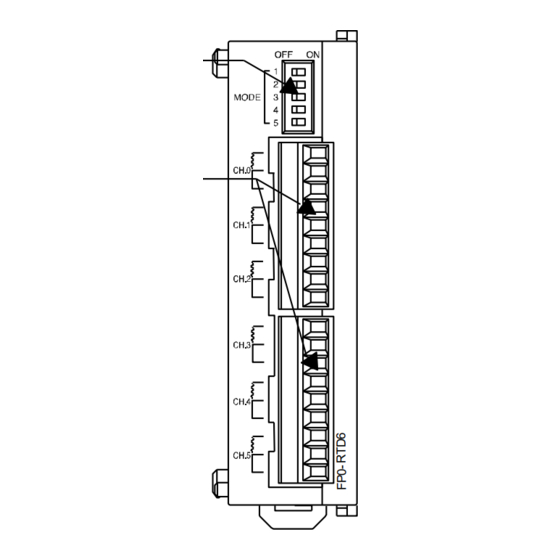
Unit Outline For further information, see page 13, I/O Allocation and Sample Programs. 1.4 Part Names and Functions FP0 RTD unit, front and left views 1. Input range setting switch DIP switches to change between the input ranges (RTD types). - Page 8 Unit Outline FP0 RTD Unit 4. DIN rail attachment lever The unit can be installed to the DIN rail by one-touch operation. The DIN rail attachment lever is also used for installing the unit to the slim 30 type mounting plate (AFP0803).
-
Page 9: Input Range Setting Switch
FP0 RTD Unit Input Range Setting Switch 2 Input Range Setting Switch Input range setting switch MODE The following switch settings are read once when the CPU is turned on. To change the settings, the CPU must be turned off. -
Page 10: Wiring
Wiring FP0 RTD Unit 3 Wiring Wiring method Input line wiring Keep a distance of more than 100mm between the input line and the power line/high-voltage line. -
Page 11: Conversion Characteristics
FP0 RTD Unit Conversion Characteristics 4 Conversion Characteristics The measurement range available for degrees Celsius is larger than for degrees Fahrenheit as the digital value (temperature value displayed) for °F is higher than the one for °C. 4.1 Pt100 Input range:-200.0°C to 500.0°C/-328.0°F to 800.0°F, resolution: 0.1K/0.1°F... - Page 12 Conversion Characteristics FP0 RTD Unit Input range:-80.00°C to 80.00°C/-80.00°F to 80.00°F, resolution: 0.01K/0.01°F 8191 8000 -8000 -80.00 80.00 (°C/°F) Input value A/D conversion table Analog input Digital output Analog input Digital output value (°C) value value (°F) value -80.00 -8000 -80.00...
- Page 13 FP0 RTD Unit Conversion Characteristics 4.2 Pt1000 Input range: -200.0°C to 300.0°C/-328.0°F to 572.0°F, resolution: 0.1K/0.1°F 8191 8191 5720 3000 -2000 -3280 -328.0 572.0 (°F) -200.0 300.0 (°C) Input value Input v alue A/D conversion table Analog input Digital output...
- Page 14 Conversion Characteristics FP0 RTD Unit Input range: -80.00°C to 80.00°C/-80.00°F to 80.00°F, resolution: 0.01K/0.01°F 8191 8000 -8000 -80.00 80.00 (°C/°F) Input value A/D conversion table Analog input Digital output Analog input Digital output value (°C) value value (°F) value -80.00 -8000 -80.00...
- Page 15 FP0 RTD Unit Conversion Characteristics 4.3 Ni1000 Input range: -30.0°C to 150.0°C/-22.0°F to 302.0°F), resolution: 0.1K/0.1°F 8191 8191 3020 1500 -300 -220 -30.0 150.0 (°C) -22.0 302.0 (°F) Input value Input value A/D conversion table Analog input Digital output Analog input Digital output value (°C)
-
Page 16: Resistor
Conversion Characteristics FP0 RTD Unit Input range: -30.00°C to 80.00°C/-22.00°F to 80.00°F, resolution: 0.01K/0.01°F 8191 8191 8000 8000 -2200 -3000 -30.00 80.00 (°C) -22.00 80.00 (°F) Input value Input value A/D table Analog input Digital output Analog input Digital output value (°C) - Page 17 FP0 RTD Unit Conversion Characteristics A/D conversion table Digital output value Analog input value () +2200 +2200 Processing if the input value range is exceeded Digital output value Analog input value () +19 or less 16383 +2201 or more Resistor broken Input range: 20.0...
-
Page 18: O Allocation And Sample Programs
FP0 RTD Unit 5 I/O Allocation and Sample Programs 5.1 I/O Numbers Up to three expansion units including the FP0 RTD unit can be connected to the CPU (2 words [2x16 bits] are assigned to each WX and WY). I/O Numbers... - Page 19 Conversion data switch flags The analog unit has a 12-bit resolution. Before the data from the FP0 RTD unit is transferred to the control unit, the data for WX3 is converted to 16-bit data as bits E and F are used as conversion data switch flags.
- Page 20 I/O Allocation and Sample Programs FP0 RTD Unit A simple way of processing positive and negative data is shown in the programming examples on the following pages. Assignment of outputs Y20…Y27 °C °F CH0: 0.1°C/°F CH0: 0.01°C/°F CH1: 0.1°C/°F CH1: 0.01°C/°F CH2: 0.1°C/°F...
-
Page 21: Programming With Fpwin Pro
FP0 RTD Unit I/O Allocation and Sample Programs 5.2 Programming with FPWIN Pro Control FPWIN Pro provides convenient function blocks (“Unit_AnalogInput_FP0_RTD_INT” and “Unit_AnalogInput_FP0_RTD_REAL”) to read data from the input channels. They can be used for all RTD types (Pt100, Pt1000, Ni1000, and Resistor). You can find the function blocks in the FP tool library. -
Page 22: Programming With Fpwin Gr
5.3.1 RTD Types Pt100, Pt1000, Ni1000 Ladder program to read data from input channels This program shows you how to store temperature data for CH0 to CH5 of the FP0 RTD unit installed as expansion unit no.1 in data registers DT0 to DT5. -
Page 23: Rtd Type Resistor
5.3.2 RTD Type Resistor Ladder program to read data from input channels This program shows you how to store temperature data for CH0 to CH5 of the FP0 RTD unit installed as expansion unit no.1 in data registers DT0 to DT5. -
Page 24: When An Error Occurs
For further information, see page 4, Input Range Setting Switch and page 13, I/O Allocation and Sample Programs. 6.2 Digital Value When Out Of Measuring Range When the input of the FP0 RTD unit is out of the measuring range, the following digital values are displayed: Pt100 [°C/°F] Pt1000 [°C/°F]... -
Page 25: Specifications
FP0 RTD Unit Specifications 7 Specifications General specifications Parameter Specifications Increase of current 25mA or less (24V DC) consumption in control unit 0°C to +55°C Operating temperature Storage -20°C to +70°C temperature Operating 30% RH to 85% RH (no condensing) - Page 26 Specifications FP0 RTD Unit Input specifications Parameter Specification Input channels Up to 6 channels per unit -200.0°C to 500.0°C Input range Resolution 0.1 -328.0°F to 800.0°F (see note 1) Pt100 -80.00°C to 80.00°C Resolution 0.01 -80.00°F to 80.00°F (see note 1) -200.0°C to 300.0°C...
- Page 27 4. These are the settings of the input channel selection switch. 5. The control unit reads data from 2 channels in one scan. Read data by using the programs described above. 6. This address applies when the FP0 RTD unit is installed as expansion unit no. 1. Block diagram...
-
Page 28: Dimensions
Dimensions FP0 RTD Unit 8 Dimensions (10) (mm) -
Page 30: Index
Index Programming ........16 Function block ......... 16 16383 digital output value ......12 I/O allocation ........... 13 I/O numbers ..........13 Input channels ........13, 21 8191 Input range ..........21 digital output value ..6, 7, 8, 9, 10, 11 Input range setting switch ..... - Page 31 RTD types ..........1 Vibration resistance ........ 20 Sampling cycle ........21 Shock resistance ........20 Weight ............. 20 Specifications .......... 20 Wires ............2 Storage humidity ........20 Wiring ............5 Storage temperature ....... 20 Troubleshooting ........19...
- Page 32 Record of Changes Manual No. Date Description of Changes ACGM0159V10END Sept. 2004 First Edition ACGM0159V11END Sept. 2006 Update company name and Web site. ACGM0159V12END Dec. 2006 Minor restructuring in preparation for localization. ACGM0159V13END Dec. 2008 Minor errors corrected: vibration resistance parameter 0.75mm; under conversion data switch flag, behavior of WX2 and WX3.
Need help?
Do you have a question about the FP0 RTD Unit and is the answer not in the manual?
Questions and answers