Table of Contents
Advertisement
Quick Links
Advertisement
Table of Contents

Subscribe to Our Youtube Channel
Related Manuals for Pilz SDD ES ETH

Summary of Contents for Pilz SDD ES ETH
- Page 1 SDD ES ETH PSEN sensor technology Operating Manual-1003824-EN-06...
- Page 2 Preface This document is the original document. All rights to this documentation are reserved by Pilz GmbH & Co. KG. Copies may be made for the user's internal purposes. Suggestions and comments for improving this documenta- tion will be gratefully received.
-
Page 3: Table Of Contents
RJ45 connection cable ......................Process data exchange ......................System structure ........................Set IP address .......................... Operation ..........................Display ............................Structure ........................... Operate menu........................... Menu structure .......................... Menu settings ........................... Device History menu......................... Device Info menu........................Operating Manual SDD ES ETH 1003824-EN-06... - Page 4 Web server ..........................Events of Safety Device Diagnostics ..................Dimensions in mm ......................... Tecnical details ........................Supplementary data ......................Network data..........................Order reference ........................Product ............................. Accessories ..........................EC declaration of conformity ....................Operating Manual SDD ES ETH 1003824-EN-06...
-
Page 5: Introduction
SDD ES ETH Introduction Validity of documentation This documentation is valid for the product SDD ES ETH. It is valid until new documenta- tion is published. This operating manual explains the function and operation, describes the installation and provides guidelines on how to connect the product. -
Page 6: Overview
Overview Scope of supply Fieldbus module SDD ES ETH Unit features SDD ES ETH is an active subscriber (Master) of Safety Device Diagnostics Backlit display LEDs for – Supply voltage – Fieldbus interface – Safety states and diagnostic information for the safety devices –... -
Page 7: Front View
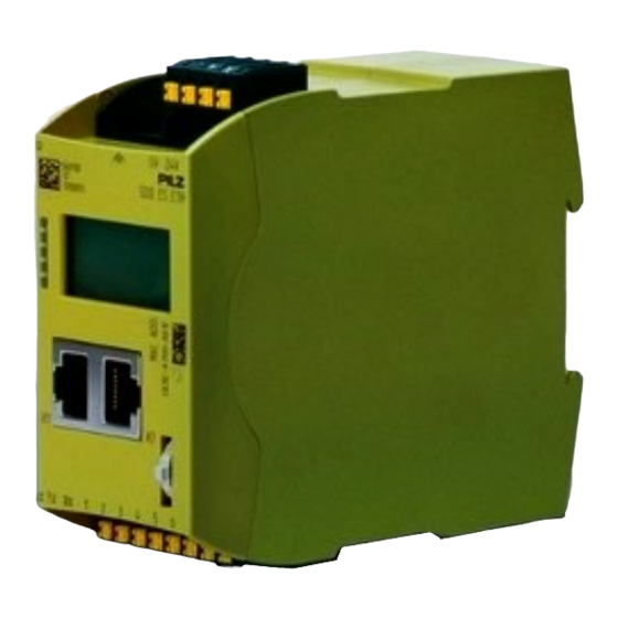
1 – 6: Configurable inputs/outputs for connecting signal inputs/out- puts from additional devices (not incorporated in safety device dia- gnostics) [1] LED Power [2] LED ModbusTCP [3] LED Devices [4] LED Start up [5] LED Fault [6] Display [7] Multifunction switch Operating Manual SDD ES ETH 1003824-EN-06... -
Page 8: Safety
Safety Intended use The SDD ES ETH is used for communication between connected safety devices and the Modbus/TCP. The Modbus/TCP is designed for data exchange at field level. The SDD ES ETH operates as the Server; a connected control system operates as the Client. -
Page 9: Safety Regulations
Safety regulations Additional documents that apply Please read and take note of the following documents: Operating manual for the relevant Pilz safety device Operating manual of a passive junction, for example: – PSEN ix2 F4 code – PSEN ix2 F8 code –... -
Page 10: Security
Perform a risk assessment in accordance with VDI/VDE 2182 or IEC 62443-3-2 and plan the security measures with care. If necessary, seek advice from Pilz Customer Support. Implemented security measures The web application is protected against unauthorised access by a password prompt. -
Page 11: Function Description
LEDs indicate the status of the SDD ES ETH and communication between the safety devices and Modbus/TCP Client. The SDD ES ETH sends telegrams to the connected safety devices via a ring protocol. The following types of data are transferred to the fieldbus and read in. -
Page 12: Data Structure
The IP address is set on the display with the multifunction switch. Data structure The input and output data is divided into the following data areas: Data for the overall system and for the SDD ES ETH Data for the connected safety devices List of specified changes of state and events... -
Page 13: Installation
The autosensing switch automatically detects whether data transfer is occurring at 10 Mbit/s or 100 Mbit/s. INFORMATION The connected subscribers must support the autosensing/autonegotiation function. If not, the communication partner must be set permanently to "10 Mbit/s, half duplex". Operating Manual SDD ES ETH | 13 1003824-EN-06... -
Page 14: Requirements Of The Connection Cable And Connector
RD- (Receive-) RD+ (Receive+) TD+ (Transmit+) n.c. n.c. n.c. n.c. RD- (Receive-) TD- (Transmit-) n.c. n.c. n.c. n.c. RJ45 connection cable RJ45 connector 8-pin 10BaseT cable or 100BaseTX cable max. 100 m Operating Manual SDD ES ETH | 14 1003824-EN-06... -
Page 15: Process Data Exchange
The RJ45 interfaces on the internal autosensing switch enable process data to be ex- changed with other Ethernet subscribers within a network. The product SDD ES ETH can also be connected to Ethernet via a hub (hub or switch). Hub/Switch... -
Page 16: System Structure
Set IP address When setting the IP address, please note: The IP address for the fieldbus module SDD ES ETH should not be the same as the PC's IP address. The following different options are available for setting the IP address. -
Page 17: Operation
23]. If a fixed IP address has been assigned via the web server, then this will be used. Operation The SDD ES ETH is ready for operation when the "Power" LED is lit and the "Fault" LED is unlit. Legend... -
Page 18: Display
Status of bus connection: No connection Press the multifunction switch to switch to the first menu level. Power Settings Device History Device Info Device Event Legend [1] Display of LED supply voltage [2] Display of menu levels Operating Manual SDD ES ETH | 18 1003824-EN-06... -
Page 19: Operate Menu
Description Settings Information about I/O mapping on the connected safety devices and about the network configuration of the SDD ES ETH Device History Information about previous changes of state (en- ables and guard locking) of a connected safety device and status information... -
Page 20: Menu Settings
Display or change the set Gateway address Changes will only take effect when SDD ES ETH is restarted. Restart Trigger a restart of the SDD ES ETH in order to ad- opt the amended IP configuration settings. Info Option Meaning... -
Page 21: Device History Menu
Actuator is within the response range Actuator is not within the response range in sec Time at which the safety gate was opened (seconds since power-on) Lock Guard locking activation Guard locking activation Operating Manual SDD ES ETH | 21 1003824-EN-06... -
Page 22: Device Info Menu
Actuator not within the response range Lock Status of guard locking activated deactivated OSSD1 Status of OSSD1 ON state OFF state OSSD2 Status of OSSD2 ON state OFF state INPUT1 Status Input 1 Operating Manual SDD ES ETH | 22 1003824-EN-06... -
Page 23: Device Event Menu
28]) Web server A web server is implemented in the fieldbus module SDD ES ETH. This can be used to poll data from the SDD. The web server is started once the SDD ES ETH is connected to the supply voltage. - Page 24 Updated by reload: this page is updated by reloading the page in the browser. Device Info The information available about the connected safety devices on the SDD ES ETH is dis- played. Updated automatically: this page is updated automatically every second.
- Page 25 – User = User – Password = 1111 Once logged in, you can log out again with logout. Logout occurs automatically when the SDD ES ETH is restarted or the browser is closed. Delete the list of events (see Delete Events [ 26]) The Settings area can be used by 2 users simultaneously.
- Page 26 Click Abort if no events are to be deleted. Set new Password A new password should be set after the SDD ES ETH is switched on for the first time. Enter the old password in the Old Password field and enter the new password in the New Password field.
- Page 27 1. Set the IP address of the configuration PC to the address range of the SDD ES ETH (e.g. 192.168.0.1). To access SDD ES ETH, the IP address of the PC has to be in the same subnet as the IP address of SDD ES ETH Change the IP address in the network settings of your configuration PC or change the IP address of the SDD ES ETH (see Set IP address).
-
Page 28: Events Of Safety Device Diagnostics
New actuator has been taught in Switch supply voltage off and then on again. Lock 0x320 Guard locking could not be activ- ated or deactivated. Check the wiring of the control and the actuator. Operating Manual SDD ES ETH | 28 1003824-EN-06... - Page 29 Check the wiring and switch the voltage off and then on again. Power ↑, please ↓ 0x908 Supply voltage above the permit- ted range (see Technical details for safety device) Reduce the supply voltage. Operating Manual SDD ES ETH | 29 1003824-EN-06...
-
Page 30: Dimensions In Mm
(see Technical details for safety device) Increase the supply voltage. Escape Release 0x90A The escape release was operated. Reset the safety device to nor- mal operation. Dimensions in mm 45 (1,8") Operating Manual SDD ES ETH | 30 1003824-EN-06... - Page 31 SDD ES ETH 96 (3,78") Operating Manual SDD ES ETH | 31 1003824-EN-06...
-
Page 32: Tecnical Details
Device type Server Permitted address range MODBUS/TCP port 1 - 65535 Operating mode Auto-MDIX, Autonegotiation Default port MODBUS/TCP Transmission rates 10 MBit/s, 100 MBit/s Galvanic isolation Times Supply interruption before de-energisation 20 ms Operating Manual SDD ES ETH | 32 1003824-EN-06... - Page 33 35 x 7,5 EN 50022 Material Bottom Front Connection type Spring-loaded terminal, plug-in, screw terminal, plug-in Conductor cross section with screw terminals 1 core flexible 0,25 - 2,5 mm², 24 - 12 AWG Operating Manual SDD ES ETH | 33 1003824-EN-06...
-
Page 34: Supplementary Data
Fieldbus module ETH for Safety Device Diagnostics 540 130 Accessories Product type Features Order no. SDD ES SET Screw terminals, plug-in 540 120 SCREW TERMIN- SDD ES SET Spring-loaded terminals, plug-in 540 121 SPRING LOADED TERMINALS Operating Manual SDD ES ETH | 34 1003824-EN-06... -
Page 35: Ec Declaration Of Conformity
EC declaration of conformity This/(These) product(s) fulfil the requirements of the low voltage directive 2006/95/EG. The complete EC Declaration of Conformity is available on the Internet at www.pilz.com/down- loads. Representative: Norbert Fröhlich, Pilz GmbH & Co. KG, Felix-Wankel-Str. 2, 73760 Ost-... - Page 36 We are represented internationally. Please refer to our homepage www.pilz.com for further details or contact our headquarters. Headquarters: Pilz GmbH & Co. KG, Felix-Wankel-Straße 2, 73760 Ostfildern, Germany Telephone: +49 711 3409-0, Telefax: +49 711 3409-133, E-Mail: info@pilz.com, Internet: www.pilz.com...
Need help?
Do you have a question about the SDD ES ETH and is the answer not in the manual?
Questions and answers