Table of Contents
Advertisement
Quick Links
Advertisement
Table of Contents

Related Manuals for Delta A3000


Summary of Contents for Delta A3000
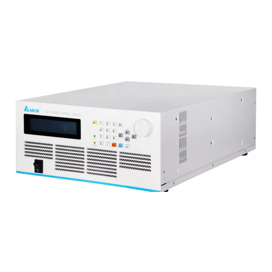
- Page 1 A3000 AC Power Source User Manual www.deltaww.com...
-
Page 2: Table Of Contents
User Manual A3000 AC Power Source Warranty ................................. 1 Warranty Coverage ............................1 Safety Summary ............................1 Safety Symbols .............................. 2 Accessories ..............................3 Revision History ............................4 1. General Information ..........................5 1.1 Introduction ............................5 1.2 Key Features ............................5 1.3 Specifications ............................ - Page 3 3.6 CONFIG Function ..........................27 3.6.1 Waveform A, B Generator ......................28 3.6.2 GPIB, RS232 Communication Setting ..................30 3.6.3 Inhibit Output by Remote Control Signal(Remote Inhibit) ............. 32 3.6.4 Power On State ......................... 34 3.7 Protection ............................35 3.8 Applications ............................37 3.8.1 Introduction ..........................
-
Page 4: Warranty
Delta electronics branches to get service. Warranty Coverage Warranty Coverage 1. Products repaired or altered by persons not authorized by Delta, or not in accordance with instructions provided by Delta. 2. Products failure caused by nature disaster or hazardous / dangerous environments: earthquake, typhoon, thunder-strike, voltage abnormal, collusion chemical, oil, in the presence of mice or bugs. -
Page 5: Safety Symbols
User Manual A3000 AC Power Source PROTECTIVE GROUNDING Make sure to connect the protective grounding to prevent an electric shock before turning on the power. NECESSITY OF PROTECTIVE GROUNDING Never cut off the internal or external protective grounding wire, or disconnect the wiring of protective grounding terminal. -
Page 6: Accessories
A3000 AC Power Source Accessories Please check the following accessories are included and not damaged during shipment. If there are damaged or shortage of the accessories, please contact Delta Electronics or sales agent for help. Note 1. standard parts. ■... -
Page 7: Revision History
User Manual A3000 AC Power Source Revision History The following list indicates the additions, deletions and modifications in this manual at each revision. Version Date Revised section June 13th, 2018 │ www.deltaww.com... -
Page 8: General Information
1.1 Introduction This manual describes the specifications, installation and operation instructions of Delta A3000 SERIES Programmable AC Power Source. In this manual the term, AC Source, stands for Delta A3000 SERIES Programmable AC Source. The series of AC source is a high efficiency programmable ac power source, which provide low distortion sinusoid AC voltage output and measurement. - Page 9 User Manual A3000 AC Power Source Resolution 0.1V Distortion 1% (30Hz~1kHz) Line Regulation 0.1% Load Regulation 0.1% Temp. coefficient 0.02% per ℃ from 25℃ Current Accuracy (rms) 0.4%+0.3%F.S. Accuracy (peak) 0.4%+0.6%F.S. Resolution 0.01 A Max. current 30A / 15A(150V/300V) peak 90A / 45A(30Hz~1kHz) 75A / 38A(>100Hz~1kHz)
-
Page 10: Name Of Parts
User Manual A3000 AC Power Source 1.4 Name of Parts 1.4.1 The Front Panel Figure 1-1 the Front Panel Front Panel Description Item Symbol Description LCD panel, display setting and measurement results. LED indicator: • OUT(green)indicates AC source normal output Recall •... -
Page 11: The Rear Panel
User Manual A3000 AC Power Source Back to local control in remote mode Negative sign in panel control At main manual page, press this key to enter "advanced parameter setting" page;at other pages, press this key to return to main... - Page 12 User Manual A3000 AC Power Source Rear Panel Description Item Name Description Mark RS-232 D type 9Pin female connector, for remote control. GPIB connector IEEE 488 standard connector, for remote control. TTL I/O The 9-pin, D-type female connector conveys TTL signals (AC_ ON, FAULT_OUT and REMOTE_INHIBIT).
-
Page 13: Installation
Save all packing materials in case the instrument has to be returned. If any damage is found, please file a claim against the carrier immediately. Do not return the instrument to the factory without obtaining the prior RMA acceptance from Delta. 2.2 Preparation for Use Before start using, the instrument must be connected with an appropriate AC line input. - Page 14 User Manual A3000 AC Power Source *** CAUTION *** To protect operators the wire connected to the GND terminal must be connected WARNING to the ground. Under no circumstances shall this AC source be operated without an adequate ground connection.
-
Page 15: Output Connection
User Manual A3000 AC Power Source 2.4 Output Connection 2.4.1 Output connection The output terminal block is located at the rear of the AC source. Load connecting to the "N" and "L" is done at the output terminals. To meet the safety requirements, the safety cover must be fasten. -
Page 16: The Procedures To Power-On
User Manual A3000 AC Power Source 2.6 The Procedures to Power-on *** CAUTION *** Before turning on the instrument, all protective earth terminals, extension cords, and devices connected to the instrument must be connected to a WARNING protective ground. Any interruption of the protective grounding will cause a potential shock hazard that might injure people. -
Page 17: Local Operation
Then will enter main manual setting page as below. Operator can set output voltage and frequency for three phase. 3.2 Operation through Keypad and Knob A3000 series provides a user-friendly programming interface by using the keypad on the front panel. Save... - Page 18 User Manual A3000 AC Power Source At the list selection manual as above, user can press numerical key to do the selection, then press to enter advanced parameter setting manual. After entering advanced Enter Save Recall setting manual, press to move cursor to item which wants to modify, use ▲...
- Page 19 User Manual A3000 AC Power Source The command tree is shown as below: MAIN PAGE MENU 1.SETUP V Limit I Limit I Limit Delay Voltage Level Voltage Sense Degree On Degree Off I Spike Start I Spike Interval Waveform Buzzer...
-
Page 20: Main Manual Setting
User Manual A3000 AC Power Source 3.3 Main Manual Setting After the AC source is on and initialization is finished, screen will show the main manual. Default output voltage and frequency is 110V and 60Hz. Voltage and frequency setting are shown on the left side of the screen, the right side of the screen shows the measurement value, example shown as below. -
Page 21: Advanced Parameter Setting Manual
User Manual A3000 AC Power Source 3.4 Advanced Parameter Setting Manual Press at main manual to enter advanced parameter setting manual. User can choose item 1~6, then press enter detail setting manual;Or Enter Menu/ press back to main manual. Home... -
Page 22: Voltage Limit
User Manual A3000 AC Power Source 3. Press back to previous page Page up Page down Definitions for all parameters are listed as below: Setting Range Parameter Definition Unit V Limit Maximum voltage setting for all 150.0 / 300.0 pages... -
Page 23: I Limit, Ocp Delay
User Manual A3000 AC Power Source The process to set Voltage Limit = 200V shows as below: Save Save Recall Recall 1. Press to move cursor to V Limit ▲ ▲ ▼ ▼ 2. Change to 200.0V by numerical key or knob, press Enter 3.5.2 I Limit, OCP Delay... - Page 24 User Manual A3000 AC Power Source Operation for I Limit is 3A,OCP delay time is 1.5s shows as below: Save Save Recall Recall 1. Press to move cursor to I Limit ▲ ▲ ▼ ▼ 2. Change to 3A by numerical key or knob, then press key to confirm the setting...
-
Page 25: Voltage Level Setting
AC Power Source 3.5.3 Voltage Level Setting A3000 SERIES provide two output voltage levels used for low voltage and high voltage applications. At 300V level, AC source can provide 16.0A in total;At 150V level 32.0A in total can be provided, maximum output power is 3000VA. -
Page 26: Degree On, Off
3.5.5 Degree On, Off A3000 SERIES can control the start phase angle (Degree On) or stop phase angle (Degree Off) of the output voltage waveform. Range for Degree On is 0.0~359.9, and is 0.0~360.0 for Degree Off. When Degree Off parameter is 0, the output stopped immediately no matter which output status is at. -
Page 27: Is Start, Is Interval
User Manual A3000 AC Power Source 4. Change parameter to 200 by numerical key or knob rotating, then press Enter confirm the setting 3.5.6 Is Start, Is Interval Both the parameter ranges for Is Start and Is Intervals are 0.0~1000.0 msec, these parameters are used for the surge current measurement. -
Page 28: Waveform Selection
3.5.7 Waveform Selection A3000 SERIES provide two sets built in waveforms A and B. User can select Sin, CSin, or other self-defined waveform from A or B set at CONFIG page, then go to SETUP page to set output voltage waveform for main manual. -
Page 29: Buzzer
User Manual A3000 AC Power Source 2.Rotate knob to change <A>to<B>, press to confirm Enter PS:Press at main manual, only A or B can be selected. If using List function, then A or B waveform can be output alternatively. 3.5.8 Buzzer When user press numerical key or rotate knob, there is sound from buzzer to confirm the... -
Page 30: Disable (Lock) The Keys At Front Panel
User Manual A3000 AC Power Source 3.5.9 Disable (Lock) the Keys at Front Panel A3000 SERIES allow the user to lock the parameters at front panel to avoid being Menu/ changed accidently. After the parameters are locked, only keys are... -
Page 31: Waveform A, B Generator
Output status for next time after AC on ON / OFF 3.6.1 Waveform A, B Generator A3000 SERIES provide memories to store group A and B waveforms, both A and B groups have waveforms as below Sinusoidal(Sine) Cut sinusoidal(Cut Sine)... - Page 32 User Manual A3000 AC Power Source Following processes demonstrate how to set group A waveform as built in waveform number 20: Save Save Recall Recall 1. Press to move cursor to Wave A ▲ ▲ ▼ ▼ 2. Rotate Knob to change <SIN>to<DST20>, press to confirm the change...
-
Page 33: Gpib, Rs232 Communication Setting
4. By pressing numerical key or rotating knob, change parameter to 1.300, press Enter confirm the setting 3.6.2 GPIB, RS232 Communication Setting A3000 SERIES provide remote control operation, there are GPIB or RS232 interface for selection. Only one interface can be activated at the same time: Remote Controller... - Page 34 User Manual A3000 AC Power Source Parameters setting for two interfaces: GPIB RS232 Address Odd/Even parity check Baud rate(Baud Rate) (Parity) 1~30 Even parity check(EVEN) 9600 Odd parity check(ODD) 19200 No parity check(NONE) Example how to set GPIB Address to 20:...
-
Page 35: Inhibit Output By Remote Control Signal(Remote Inhibit
TTL signal Remote Control When both front panel and remote control are idle, output of A3000 SERIES is according to external TTL ON/OFF signal. When user press 「OUT」 from front panel or by remote control, TTL signal has no effect on the operation. - Page 36 Time Time TRIG:TTL signal changes from HIGH → LOW, and keeps low longer than 1ms, A3000 SERIES turn off output, and stop detecting TTL signal, output stays at off state even TTL signal changes to high. User must press...
-
Page 37: Power On State
Enter 3.6.4 Power On State A3000 SERIES may set different operation modes or enable turn on output immediately next time after AC is on. Output voltage and frequency depend on stored parameter before AC input is off. -
Page 38: Protection
3.7 Protection A3000 SERIES provide software and hardware protections. A3000 SERIES will disconnect output relay to turn off output and display protection status on screen when protection happens. To resume the output, following three errors can be released by long press any key. - Page 39 PFC PG Fault Output abnormal for PFC Board Notes: 1.A3000 SERIES has one no fuse breaker at AC input side, its current rating is 20A. AC source will enter protection status when AC input current is over 20A. 2.D2A OCP ranges:When Voltage Level is 300V, OCP trigger point is 16A.
-
Page 40: Applications
PULSE mode:Simulate repeatedly changed output voltage. STEP mode:Simulate gradually changed output voltage. A3000 SERIES also provide 39 orders of amplitude and phase angle settings for user to make self-defined waveforms. It can be used at all output modes once the self-defined waveforms is created. - Page 41 User Manual A3000 AC Power Source LIST mode provide 10 sets of programmable waveform(SEQ-0 ~ SEQ-9). Output waveforms start from SEQ-0, then SEQ-1、SEQ-2… in orders until time parameter (Time) of SEQ-n being processed is 0 or SEQ-9 is finished outputting, then one List waveform output is completed.
- Page 42 User Manual A3000 AC Power Source Trigger ON ⁄ OFF is output switch for List waveform, output status is current output status. At this page, there are two modes: 1. To output List waveform Press to start output List waveform. Screen will show information as below Enter during output is in process:...
- Page 43 User Manual A3000 AC Power Source There are two ways to leave Trigger page: ESC/ Under output is off, press will back to LIST initialization page. Cancel Menu/ Press will back to main manual. Home LIST mode example:...
-
Page 44: Pulse Mode
User Manual A3000 AC Power Source Output waveform: SEQ - 0 SEQ - 1 45° 72 ms 100 ms 3.8.3 PULSE Mode 1. At advanced parameter setting page, press 4 to select PULSE 2. Press to enter PULSE page Enter... - Page 45 User Manual A3000 AC Power Source PULSE mode lets user insert fixed period, programmed special waveform to output waveform set at main manual. Range Parameter definition Count How many times to output programmed Pulse waveform. 10000 If setting is 0, Pulse waveform will output endless...
- Page 46 User Manual A3000 AC Power Source When the output state of AC source is triggered, pressing key can stop the output. Press button again, the AC source will output the waveform according to the main page setting. Then press key, the output state can be triggered from the main page Enter output state to the PULSE mode output state.
-
Page 47: Step Mode
User Manual A3000 AC Power Source 3.8.4 STEP Mode 1. At advanced parameters setting page, press 5 to select STEP 2. press to enter STEP page Enter Voltage and frequency are same for each step in STEP mode, but may be different in different steps. - Page 48 User Manual A3000 AC Power Source Select Go to Trigger Mode, press to enter Trigger page shown as below: Enter "Trigger On" represents that the trigger is ready. "Stop" is the current output state. Press key to trigger. And then the screen will display "Trigger OFF" and "Running"...
- Page 49 User Manual A3000 AC Power Source STEP mode example: Parameter setting: Output waveform: │ www.deltaww.com...
-
Page 50: Synthesis Self-Defined Waveform Mode
User Manual A3000 AC Power Source 3.8.5 SYNTHESIS Self-Defined Waveform Mode 1. At advanced parameters setting page, press 6 to select SYNTHESIS 2. Press key to enter SYNTHESIS page Enter WAVEFORM: AC power supply provides two self-defined waveforms for user to set. The waveforms are DIS30 and DIS31. - Page 51 User Manual A3000 AC Power Source Press to enter the next page, as shown below. Page up Page down ESC/ After finishing setting, press key to return to the initial page. Select "Save Synthesis Cancel Parameter" to complete the setting.
-
Page 52: Save And Recall Functions
AC power supply provides two modes for users to save and recall the output setting or the system information. 3.9.1 Save and Recall the Main Page Setting A3000 SERIES provides 9 channels for users to save V and F. Users can save or recall the specific parameters at any time. 3.9.1.1 Save the Main Page Setting Following is the example of saving V=150V and F=80Hz to Channel 2 Memory. -
Page 53: Save And Recall The System Setting
V Limit. 3.9.2 Save and Recall the System Setting A3000 SERIES provides 3 groups of memory for users to save the system data. System data contains the parameters in SETUP and CONFIG pages. First, entering the PAGE SELECT screen, as shown below. -
Page 54: Save System Setting
User Manual A3000 AC Power Source 3.9.2.1 Save System Setting Save Recall 1. Press key about 2 seconds in "PAGE SELECT" page, then it will enter the ▲ ▼ system data storage mode, as shown below. 2. Choose a group of Group 1 to Group 3 and press... -
Page 55: Recall System Setting
User Manual A3000 AC Power Source 3.9.2.2 Recall System Setting Save Recall 1. Press key about 2 seconds in "PAGE SELECT" page, then it will enter the ▲ ▼ system data recalling mode, as shown below. 2. Choose a group of Group 1 to Group 3 and press... -
Page 56: Remote Operation
4. Remote operation 4.1 Introduction A3000 SERIES can be remotely controlled by GPIB or RS-232. GPIB interface is an 8-bit parallel data bus with other control lines to manage communication. RS-232 transmits data in series so communication speed is slower. -
Page 57: Programming
The Boolean parameter <Boolean> uses the form ON|OFF only. 4.2.4 Basic Definition of Command Construction of A3000 SERIES remote control command is based on tree system, every command must have a full path so instrument can receive it. Tree structure use ”:” as node. Command or data at left side of node is in higher level while at right side is in detail level. - Page 58 A3000 AC Power Source A3000 SERIES includes two distinctive types of command. The first one is command described in IEEE 488.2, it is common commands for GPIB, represented by ”* ” at beginning of the command. The second one is instruments self-defined commands. All commands are not upper/ lower case sensitive.
-
Page 59: Command For Remote Control
User Manual A3000 AC Power Source 4.3 Command for Remote Control 4.3.1 IEEE 488.2 Standard Command *ESE <n> Set flag mask of standard event status register. This command is for a register used for IEEE488.2 defined standard events. It is used for flag mask or control enable. Set by 1 enables target event detection, and event detection is masked if setting is 0. -
Page 60: Instrument Commands
User Manual A3000 AC Power Source *SRE? Return status of flag mask status for service events. *STB? Query value stored in service event register, 1 represents event occurs. *CLS Clear status. Following operation may execute depends on different conditions. 1. Leave REMOTE control, back to panel control. - Page 61 User Manual A3000 AC Power Source :REACtive? Query total reactive power :VOLTage :ACDC? Query average AC Vrms Following examples explain FETCH and MEASURE command and returned parameter: FETCh:CURRent:AC? MEASure:CURRent:AC? Function :Query total output AC Irms. Example :FETCh:CURRent:AC? MEASure:CURRent:AC? Parameter returns :<NR2>...
- Page 62 User Manual A3000 AC Power Source Example :FETCh:CURRent:INRush? MEASure:CURRent:INRush? Parameter returns :<NR2> FETCh:FREQuency? MEASure:FREQuency? Function :Query average output frequency Example :FETCh:FREQuency? MEASure:FREQuency? Parameter returns :<NR2> FETCh:POWer:AC[:REAL]? MEASure:POWer:AC[:REAL]? Function :Query output real power Example :FETCh:POWer:AC? MEASure:POWer:AC:REAL? Parameter returns :<NR2> FETCh:POWer:AC:APParent? MEASure:POWer:AC:APParent? Function :Query output apparent power...
-
Page 63: Output Subsystem
User Manual A3000 AC Power Source FETCh:POWer:AC:REACtive? MEASure:POWer:AC:REACtive? Function :Query output reactive power Example :FETCh:POWer:AC:REACtive? MEASure:POWer:AC:REACtive? Parameter returns :<NR2> FETCh:VOLTage:ACDC? MEASure:VOLTage:ACDC? Function :Query average output voltage Vrms Example :FETCh:VOLTage:AC? MEASure:VOLTage:AC? Parameter returns :<NR2> 4.3.2.2 OUTPUT Subsystem Following are tree system for OUTPUT command:... -
Page 64: Source Subsystem
User Manual A3000 AC Power Source Example :OUTPut:MODE? Query output mode OUTPut:MODE LIST set output as LIST mode Parameter :FIXED | LIST | PULSE | STEP Parameter returns :FIXED | LIST | PULSE | STEP 4.3.2.3 SOURCE Subsystem Following are tree system for SOURCE command:... - Page 65 User Manual A3000 AC Power Source :OFF Set(query) output voltage stop phase angle set at main manual LIST :COUNt Set(query) how many times to execute effective sequences. :DWELl Set(query) execution time of each sequence :SHAPe Set(query) voltage waveform buffer of each sequence...
- Page 66 User Manual A3000 AC Power Source :COUNt Set (query) how many steps to be executed in STEP mode SYNThesis Set (query) which synthesis waveform to use. :AMPLitude Set (query) harmonic voltage amplitude of each order :PHASe Set (query) harmonic phase angle of each order...
- Page 67 User Manual A3000 AC Power Source Example : [SOURce:]CURRent:INRush:INTerval? [SOURce:]CURRent:INRush:INTerval 400.8 Parameter : <NR2>, effective range:0.0 ~ 1000.0 (unit: msec) Parameter returns :<NR2> [SOURce:]FREQuency Function : Set (query) frequency of output waveform Example : [SOURce:]FREQuency? [SOURce:]FREQuency 50.8 Parameter : <NR2>, effective range:30.0 ~ 1000.0 (unit: Hz) Parameter returns :<NR2>...
- Page 68 User Manual A3000 AC Power Source Example : [SOURce:]FUNCtion:SHAPe:A:CF? [SOURce:]FUNCtion:SHAPe:A:CF 1.234 Parameter :<NR2>,effective range:1.200 ~ 1.414 Parameter returns :<NR2> [SOURce:]FUNCtion:SHAPe:B Function :Set (query) waveform of waveform buffer B. Example :[SOURce:]FUNCtion:SHAPe:B? [SOURce:]FUNCtion:SHAPe:B CSIN Parameter :SINE | CSIN | DST<00~31> Parameter returns :SINE | CSIN | DST<00~31>...
- Page 69 User Manual A3000 AC Power Source Parameter :<NR2>,effective range:0.0 ~ 150.0 (low voltage range), 0.0 ~ 300.0 (high voltage range) Parameter returns :<NR2> [SOURce:]VOLTage:RANGe Function :Set (query) output voltage range HIGH Voltage range(V) Current range(A) Voltage range(V) Current range(A) 0.0 ~ 150.0 0.0 ~ 32.0...
- Page 70 User Manual A3000 AC Power Source Example :[SOURce:]PHASe:ON? [SOURce:]PHASe:ON 200.5 Parameter :<NR2>, effective range:0.0 ~ 359.9 Parameter returns :<NR2> [SOURce:]PHASe:OFF Function :Set (query) waveform stop phase angle set at main manual. Example :[SOURce:]PHASe:OFF? [SOURce:]PHASe:OFF 250.5 Parameter :<NR2>,effective range:0 ~ 360.0, 360.0 representing turn off immediately Parameter returns :<NR2>...
- Page 71 User Manual A3000 AC Power Source Parameter :A|B, …, A|B Parameter returns :A|B, …, A|B [SOURce:]LIST:VOLTage:AC: STARt Function : Set (query) start voltage of 10 individual sequences in LIST mode. Example : [SOURce:]LIST:VOLTage:AC: STARt? [SOURce:]LIST:VOLTage:AC: STARt 110 22.5 55.6 Parameter : <NR2>, …, <NR2> effective range:0.0 ~ 150.0 (low voltage range), 0.0 ~300.0 (high voltage range)
- Page 72 User Manual A3000 AC Power Source Parameter : <NR2>, …, <NR2> effective range:30.0 ~ 1000.0 (unit: Hz) Parameter returns :<NR2>, …, <NR2> [SOURce:]LIST:DEGRee Function : Set (query) start phase angle of 10 individual sequences in LIST mode. Example : [SOURce:]LIST:DEGRee? [SOURce:]LIST:DEGRee 30.6 96.5 88.0 71...
- Page 73 User Manual A3000 AC Power Source [SOURce:]PULSe:COUNt Function : Set (query) how many times to execute PULSE voltage. Example : [SOURce:]PULSE:COUNt? [SOURce:]PULSE:COUNt 500 Parameter : <NR1> effective range:0 ~ 10000 Parameter returns :<NR1> [SOURce:]PULSe:DCYCle Function : Set (query) execution time of PULSE waveform, it must be no longer than total period in PULSE mode.
- Page 74 User Manual A3000 AC Power Source [SOURce:]STEP:DVOLtage:AC Function : Set (query) voltage change of each step in STEP mode. Example : [SOURce:]STEP:DVOLtage:AC? [SOURce:]STEP:DVOLtage:AC 20.5 Parameter : <NR2> effective range:-150.0 ~ 150.0(unit:Volt) Parameter returns :<NR2> [SOURce:]STEP:FREQuency Function : Set (query) start frequency for STEP mode Example :...
- Page 75 User Manual A3000 AC Power Source Example : [SOURce:]STEP:DWELl? [SOURce:]STEP:DWELl 1000.5 Parameter : <NR2> effective range:1 ~ 60000.0 (unit:msec) Parameter returns :<NR2> [SOURce:]STEP:COUNt Function : Set (query) how many steps to execute in STEP mode. Example : [SOURce:]STEP:COUNt? [SOURce:]STEP:COUNt 500 Parameter :...
-
Page 76: Other Commands
User Manual A3000 AC Power Source [SOURce:]SYNThesis:PHASe Function : Set (query) phase for each order of harmonic waveforms. Example : [SOURce:]SYNThesis:PHASe? [SOURce:]SYNThesis:PHASe 100.5 20.8 60.5 77.8 Parameter : <NR2>, …, <NR2> effective range:0.0 ~ 359.9 Parameter returns :<NR2>, …, <NR2>... -
Page 77: Summary Of Commands
User Manual A3000 AC Power Source 4.3.3 Summary of Commands Common commands *ESE <n> Set flag mask of standard event status register *ESE? Query flag mask of standard event status register *ESR? Query value stored in standard event register, 1 represents event occurs. - Page 78 User Manual A3000 AC Power Source [SOURce:] CURRent :LIMit Set(query) total output rms current limitation :DELay Set(query) delay time to trigger over current protection :INRush :STARt Set(query) time to start to measure inrush current :INTerval Set(query) inrush current measurement time...
- Page 79 User Manual A3000 AC Power Source :DWELl Set (query) execution time of 10 individual sequences in LIST mode. :SHAPe Set (query) waveform buffer used for 10 individual sequences in LIST mode. :VOLTage :STARt Set (query) start voltage of 10 individual sequences in LIST mode.
- Page 80 User Manual A3000 AC Power Source :FREQuency Set(query) start frequency of the first step in STEP mode. :DFRequency Set(query) frequency change of each step in STEP mode. :SPHase Set(query) start phase angle at STEP mode. :DWELl Set(query) output duration of each step in STEP mode.
-
Page 81: Appendix A Ttl Pin Assignment
User Manual A3000 AC Power Source Appendix A TTL Pin Assignment 9-PIN D-SUB female connector number signal Remote Inhibit AC-ON FAULT-OUT Remote Inhibit: OFF : Disable remote inhibit output function. LIVE : AC source will turn off (turn on) output when TTL signal is low (high). -
Page 82: Appendix B Built In Waveforms
User Manual A3000 AC Power Source Appendix B Built In Waveforms DST 0 Order Gain Phase 2.07 9.80 15.80 2.16 DST 1 Order Gain Phase 1.50 1.50 2.00 DST 2 Order Gain Phase 2.00 1.40 2.00 1.40 1.00 │ www.deltaww.com... - Page 83 User Manual A3000 AC Power Source DST 3 Order Gain Phase 2.50 1.90 2.50 1.90 1.10 1.50 1.10 DST 4 Order Gain Phase 1.10 2.80 1.40 2.30 1.50 DST 5 Order Gain Phase 1.65 4.20 3.45 1.05 3.00 │ www.deltaww.com...
- Page 84 User Manual A3000 AC Power Source DST 6 Order Gain Phase 2.20 5.60 2.80 4.60 3.00 1.40 1.00 DST 7 Order Gain Phase 4.90 1.60 2.70 1.40 2.00 1.10 DST 8 Order Gain Phase 7.35 2.40 4.05 2.10 1.05 3.00 1.65...
- Page 85 User Manual A3000 AC Power Source DST 9 Order Gain Phase 9.80 3.20 5.40 1.20 2.80 1.40 4.00 2.20 1.40 1.40 1.60 1.40 DST 10 Order Gain Phase 17.75 DST 11 Order Gain Phase 21.25 │ www.deltaww.com...
- Page 86 User Manual A3000 AC Power Source DST 12 Order Gain Phase 24.50 DST 13 Order Gain Phase 2.30 9.80 15.80 2.50 DST 14 Order Gain Phase 1.15 4.90 7.90 1.25 │ www.deltaww.com...
- Page 87 User Manual A3000 AC Power Source DST 15 Order Gain Phase 2.45 3.95 DST 16 Order Gain Phase 11.00 180.0 4.05 2.00 180.0 1.30 DST 17 Order Gain Phase 7.17 3.42 180.0 0.80 │ www.deltaww.com...
- Page 88 User Manual A3000 AC Power Source DST 18 Order Gain Phase 8.11 3.48 180.0 1.00 DST 19 Order Gain Phase 9.38 3.44 180.0 1.15 DST 20 Order Gain Phase 2.06 180.0 1.77 1.62 180.0 1.23 0.91 180.0 0.54 0.51 0.53 180.0...
- Page 89 User Manual A3000 AC Power Source DST 21 Order Gain Phase 3.08 180.0 2.72 2.43 180.0 1.97 1.41 180.0 0.86 0.62 180.0 0.73 0.77 180.0 0.69 0.56 180.0 DST 22 Order Gain Phase 0.13 180.0 4.28 180.0 3.77 3.27 180.0 2.57...
- Page 90 User Manual A3000 AC Power Source DST 24 Order Gain Phase 7.35 180.0 6.60 5.74 180.0 4.57 3.41 180.0 2.16 1.04 180.0 0.74 1.35 180.0 1.64 1.73 180.0 1.56 1.24 180.0 DST 25 Order Gain Phase 3.41 2.55 9.22 7.68 0.90...
- Page 91 User Manual A3000 AC Power Source DST 27 Order Gain Phase 33.33 20.00 13.80 10.80 8.50 7.20 6.00 5.00 5.00 4.50 4.00 3.50 2.95 2.50 2.00 2.00 2.00 2.00 2.00 DST 28 Order Gain Phase 33.33 20.00 13.80 10.80 8.50 7.20...
- Page 92 User Manual A3000 AC Power Source DST 29 Order Gain Phase 33.33 20.00 13.80 10.80 8.50 7.20 5.50 │ www.deltaww.com...
- Page 93 Delta Electronics Ltd. 3 Tungyuan Rd., Chungli Industrial Zone, Taoyuan City 32063 TEL:+886 3 4526107 Mail:Inquiry@deltaww.com...
Need help?
Do you have a question about the A3000 and is the answer not in the manual?
Questions and answers