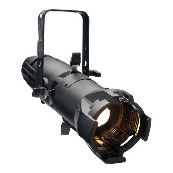
ETC Source Four Assembly Manual
Hide thumbs
Also See for Source Four:
- Assembly manual (32 pages) ,
- User manual (16 pages) ,
- Assembly instructions manual (16 pages)
Table of Contents
Advertisement
Quick Links
Assembly Guide
Production Dates: September 2004 - Present
ATTENTION:
The part numbers listed in this guide may differ from the parts
required for your particular Source Four fixture. Part numbers for
fixtures change occasionally as parts are replaced or upgraded.
To ensure that you are ordering the proper part for your specific
fixture, please contact your ETC dealer, or ETC Customer Service
for assistance.
C o p y r i g h t © E le c tr o n i c T h e a t r e C o n t r o l s , I n c .
P r o d u c t in f o r m a t i on a n d s p e c i f i c a t i o n s s u bj e c t t o c h a n g e .
P a r t N u m b e r : 7060M2500-05.02 R e v B
A l l R i g h t s r e s e r v e d .
R e l e a s e d : J u l y 2 0 0 6
Advertisement
Table of Contents

Subscribe to Our Youtube Channel
Related Manuals for ETC Source Four


Summary of Contents for ETC Source Four
- Page 1 ATTENTION: The part numbers listed in this guide may differ from the parts required for your particular Source Four fixture. Part numbers for fixtures change occasionally as parts are replaced or upgraded. To ensure that you are ordering the proper part for your specific fixture, please contact your ETC dealer, or ETC Customer Service for assistance.
-
Page 2: Table Of Contents
T a b l e o f C o n t e n t s Basic Assembly .........1 Lamp Socket Assembly . -
Page 3: Basic Assembly
Basic Assembly Figure 1 Reference Part Description Quantity Number Number Required 7060A2008 Lamp socket assembly 7060A2011 Rear housing assembly, single clutch 7060A2020 Rear housing assembly, double clutch 7060A2012 Front barrel assembly 7060A2000-K 5° lens tube, with knob (See page 7060A2001-K 10°... -
Page 4: Lamp Socket Assembly
Spring, ground 4" W420 wire, 16 gauge, 200° C/300V, green, UL 1180/CSA AWM 7060B7007 with two J490T lugs installed 7060A4037 Handle, insulated rear, black HW2181 Screw, 6-32 x 3/4, Taptite 7060A3085 Source Four Lamp Retainer Wire Source Four Assembly Guide... -
Page 5: Assemble Lamp Socket
A s s e m b l e l a m p s o c k e t Tools Required: • Open-end adjustable wrench or a 7/16” socket • Needle-nose pliers • #2 Phillips screwdriver Figure 3 Step 1: Set the crossbar of the retainer clip (25) under the two hooks on the clip bracket as shown in Figure Step 2:... - Page 6 Step 12: Install the ground spring (21) onto the screw and secure it with the Southco flat retaining ring (12). Install the Southco ring with its prongs away from the casting. Source Four Assembly Guide...
- Page 7 N o t e : Use pliers to straighten the Southco retaining ring (12) if it bends when you install it on the bolt. Step 13: Lay the leads in the bottom half of the cable clamp (located in the housing socket casting [1]), making sure that the fiberglass sleeving extends slightly past the screw holes in the housing socket casting.
-
Page 8: Reflector Housing Assembly
Rivet, machine, 3/16 x .720, flat head, black zinc HW5126 Washer, flat, 5/16, black zinc HW5193 Bolt 5/16-18 x 3/4, black zinc HW5125 Bolt, carriage, 5/16-18 x .75, black zinc HW752 Rivet machine, 3/16 x 5/16, black zinc Source Four Assembly Guide... -
Page 9: Remove Reflector
R e m o v e r e f l e c t o r Tools Required: • minimally padded work surface (cardboard, carpet, or rubber mat recommended) W A R N I N G : This procedure may crack or break the reflector. Always wear gloves, safety glasses, and a dust mask when performing this procedure. -
Page 10: Install Reflector
Remove dust with a blast of oil-free air or wipe with a clean, lint-free cloth using alcohol or distilled water (alcohol is recommended). W A R N I N G : Do not use glass and window cleaners on the reflector. Chemicals in these cleaners will stain the reflector. Source Four Assembly Guide... -
Page 11: Front Barrel Assembly
Front Barrel Assembly Figure 13 Shutter Assembly: The bottom divider plate (4) has four dimples punched into the surface; the top plate (6) has none. The middle divider plates (5) are noticeably thinner-gauge metal than the other two. See detail to the right Figure 12 Reference... -
Page 12: Assemble Front Barrel
Step 7: Place the top divider plate (6) on top of the fourth shutter blade. N o t e : Make sure no shutter assembly components are under the pattern holder guides. Source Four Assembly Guide... - Page 13 Step 8: With both front barrel castings still standing upright, join the two halves, sliding the handle of the top shutter blade through the slot in the top front barrel casting (1). Step 9: Starting at the bottom of the castings (closest to the shutters), use four PHMS screws (9) to fasten the front barrel casting halves together, as shown.
-
Page 14: 19°, 26°, 36°, And 50° Lens Tubes
HW534 Nut, hex, 1/4-20, black zinc 7060A4008-01 Knob set with male insert HW5143 Washer, flat, 1/4 7060A4033 19° lens tube label 7060A4034 26° lens tube label 7060A4035 36° lens tube label 7060A4036 50° lens tube label Source Four Assembly Guide... -
Page 15: Assemble Lens Tube (19°, 26°, 36°, And 50°)
A s s e m b l e l e n s t u b e ( 1 9 ° , 2 6 ° , 3 6 ° , a n d 5 0 ° ) Tools Required: • #2 Phillips head screwdriver Step 1: Place the left and right lens holder castings (1 &... -
Page 16: Cleaning 19°, 26°, 36°, And 50° Glass Lenses
Never use glass and window cleaner or any abrasive material to clean the lens. Glass and window cleaners will stain the lens surface. Abrasive materials (such as steel wool) will damage the surface of the lens. Step 2: Starting from the center, gently wipe the lens. Source Four Assembly Guide... -
Page 17: 10° Lens Tube
10° Lens Tube Figure 17 Reference Part Description Quantity Number Number Required 7060A3096 10° lens tube assembly, painted 7060A4009 Bushing, guide HW750 Spring, retainer HW6122 Bumper, recess rubber 7060A4025 Lens, 10°, 10" 7060A3079 Clip, gel retainer HW307 Screw, 8-32 x .38 lg, SPHMS, black zinc HW370 Nut, 8-32, 3/8, 1/4, black zinc HW3104... -
Page 18: 5° Lens Tube
Washer, .195 x .410 x .025 black zinc HW5197 Screw, 1/4, 20x58 PHRMS, black zinc HW5200 Washer, SH, .253 x .281 x .438, black zinc 7060A4008 Knob, Z lamp, with male insert HW5143 Washer, Flt. 1/4, .252 x .500 x .060, FL Source Four Assembly Guide... -
Page 19: Assemble 5° And 10° Lens Tubes
A s s e m b l e 5 ° a n d 1 0 ° l e n s t u b e s Tools Required: • #2 Phillips head screwdriver Step 1: Place the lens tube assembly (1) on your work surface. Align the assembly so that the colorframe grooves are to your left. - Page 20 Email: (Americas) mail@etcconnect.com (UK) mail@etceurope.com (DE) info@ttlicht.com (Asia) mail@etcasia.com Service: (Americas) service@etcconnect.com (UK) service@etceurope.com (Asia) service@etcasia.com Comments about this document: techcomm@etcconnect.com 7060M2500-05.02 Rev B Released 07/2006 Copyright © 2005 ETC. All Rights Reserved. Product information and specifications subject to change.
Need help?
Do you have a question about the Source Four and is the answer not in the manual?
Questions and answers