ETC Source Four User Manual
Source four fresnel
Hide thumbs
Also See for Source Four:
- Assembly manual (32 pages) ,
- Assembly instructions manual (16 pages) ,
- User manual (16 pages)
Table of Contents
Advertisement
Quick Links
®
S o u r c e F o u r
F r e s n e l
User Manual
Rev A
C o p y r i g h t © 2 0 1 1 E le c tr o n i c T h e a t r e C o n t r o l s , I n c .
A l l R i g h t s r e s e r v e d .
P r o d u c t in f o r m a t i on a n d s p e c i f i c a t i o n s s u bj e c t t o c h a n g e .
P a r t N u m b e r : 7064M1200 R e v A
R e le a s ed : 2 0 1 1 - 0 7
Advertisement
Table of Contents

Related Manuals for ETC Source Four


Summary of Contents for ETC Source Four
-
Page 1: User Manual
® S o u r c e F o u r F r e s n e l User Manual Rev A C o p y r i g h t © 2 0 1 1 E le c tr o n i c T h e a t r e C o n t r o l s , I n c . A l l R i g h t s r e s e r v e d . - Page 2 E T C pe r m i t s t h e r e p r o d u c t i o n o f m a t e r i a l s i n th i s m a n u a l o n l y f o r n o n - c o m m e r c i a l p u rp o s e s . A l l o t h e r r i g h ts a r e r e s e r v e d b y E T C .
-
Page 3: Table Of Contents
T a b l e o f C o n t e n t s Basic Assembly .........1 Lamp Information . -
Page 5: Basic Assembly
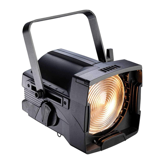
Lamp door Lamp Lamp holder base Figure-1 Source Four Fresnel fixture components. W A R N I N G : Please note the following safety warnings before use: Do not use this fixture with a damaged power lead. If the power lead (cordset) is damaged, it must be replaced. -
Page 6: Lamp Information
H P L L a m p T a b l e C A U T I O N : Do not use lamps other than the HPL in Source Four fixtures. Use of lamps other than HPL will void UL/cUL safety compliance and your warranty. -
Page 7: Installing And Replacing The Lamp
I n s t a l l i n g a n d R e p l a c i n g t h e L a m p A lamp must be installed before you use the fixture. Lamp door latch Lamp door Figure-2 Lamp door on bottom of the fixture. - Page 8 Allow to dry before operation. Step 7: Align the flat sides of the lamp base with the retention brackets on either side of the socket in the lamp holder assembly as shown in Figure-3. Source Four Fresnel User Manual...
- Page 9 Step 8: Push down on the lamp base until the lamp seats firmly. When properly installed, the top of the lamp’s base will be even with the top edges of the retention brackets. C A U T I O N : Improperly installed lamps and lamp holder assemblies cause premature lamp failure and socket problems.
-
Page 10: Field Angle Adjustment
Focus knob in 65° field angle flood position Focus knob in 20° field angle spot position Figure-5 Field Adjustment from flood to spot. Step 3: To lock the focus dial, press the locking lever into place. Source Four Fresnel User Manual... -
Page 11: Accessory Holder
Accessory Holder The accessory holder is equipped with two slots and a locking door that prevents color frames and accessories from falling out. Accessory holder locking door Figure-6 Accessory holder door in the open position. W A R N I N G : Make sure all color frames and accessories are locked in position with the accessory door before hanging the fixture. - Page 12 750w lamp. For best results, always use high-quality color media rated for high-temperature use. A variety of heat shield products is also available from many color media manufacturers. Follow the manufacturer’s instructions for the use of these products. Source Four Fresnel User Manual...
-
Page 13: Yoke Balance Point Adjustment
Yoke Balance Point Adjustment The yoke mounting position can be adjusted on the fixture to accommodate varying weights of different accessories. For example, move the yoke balance point forward (toward the lens) to balance the additional weight of a color scroller and barndoor assembly in the accessory slot. Step 1: Loosen the nuts on both sides of the yoke assembly, being sure to steady the fixture with the handle on the rear of the unit. -
Page 14: Replacing The Lens
Figure-10 Lens retaining clip. Step 4: Allow the top of the lens to drop forward from under the clips while using your hand to prevent the lens from falling. Source Four Fresnel User Manual... -
Page 15: Cleaning The Glass Lens And Reflector
Figure-11 Removing the lens. Step 5: Carefully remove the lens. I n s t a l l i n g t h e l e n s N o t e : Do not leave finger prints on the lens. Handle the lens with a soft, clean cloth. Step 1: Position the fixture with the front of the unit (lens side) facing you, and tilted slightly upward. - Page 16 Service: (Americas) service@etcconnect.com (UK) service@etceurope.com (DE) techserv-hoki@etcconnect.com (Asia) service@etcasia.com Web: www.etcconnect.com Copyright © 2011 ETC. All Rights Reserved. Product information and specifications subject to change. 7064M1200 Rev A Released 2011-07 ...
Need help?
Do you have a question about the Source Four and is the answer not in the manual?
Questions and answers