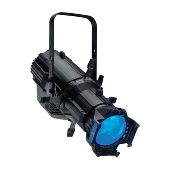
ETC source four Assembly Instructions Manual
Hide thumbs
Also See for source four:
- Assembly manual (32 pages) ,
- User manual (16 pages) ,
- Quick manual (9 pages)
Advertisement
Quick Links
Advertisement

Related Manuals for ETC source four


Summary of Contents for ETC source four
- Page 1 S O U R C E F O U R Parts List and Assembly Instructions...
- Page 2 (2 required) Final assembly 2/96 Reference Part Description Quantity Number Number Required 7060A2008 Lamp socket assembly 7060A2011 Reflector housing assembly, single clutch 7060A2020 Reflector housing assembly, double clutch 7060A2012 Front barrel assembly 7060A2000-K 5° lens tube, with knob 7060A2001-K 10° lens tube, with knob 7060A2002-K 19°...
- Page 3 (2 required) (2 required) Lamp socket assembly 2/96 Reference Part Description Quantity Number Number Required 7060A3055 Housing, socket, casting, painted 7060A3057 Socket, light baffle casting, painted 7060A4007 Knob, X-Y, lamp set 7060A4008-02 Knob, Z, lamp set w/female insert 7060A4011 Bushing, cup 7060A3011 Hub, index, casting 7060A3012...
- Page 4 Lamp socket assembly Tools required: Open-end adjustable wrench or a 7/16" socket, needle-nose pliers, screwdriver. 1. Insert the bolt (19) through the light baffle socket casting (2), then place green ground wire assemblies (21 and 24) on the end of the bolt protruding through the back of the casting. Place the ground wires through the indent in the lip surrounding the bolt hole in the casting.
- Page 5 7. Lay the leads in the bottom half of the cable clamp, making sure that the fiberglass sleeving extends slightly past the screw holes in the housing socket casting, (install new sleeving if necessary) then route the wires as shown. Important: You must follow the wire routing diagram to ensure that the socket leads do not interfere with the lamp focus mechanism.
- Page 6 (4 required) (3 required) (2 required) (2 required) (4 required) (4 required) Reflector housing assembly 2/96 Reference Part Description Quantity Number Number Required 7060A3054 Housing, reflector casting, single clutch, painted 7060A30XX Housing, reflector casting, double clutch, painted 7060A3006 Clip, reflector retainer 7060A4010 Bushing, gate 7060A3016...
- Page 7 To remove a reflector Tools required: Two spare reflector retainer clips (2). 1. Wedge one arm of a spare retainer clip between the lip of one of the installed clips figure 1 and the rim of the reflector, then slide the arm down between the installed clip and the reflector as shown in figure 1.
- Page 8 (2 required) (4 required) (4 required) (4 required) 2/96 Note: The bottom divider plate (4) has four dimples punched into the surface; the top plate (6) has none. The middle divider plate (5) is noticeably thinner-gauge metal than the other two. (4 required) (See detail to the right) 2/96...
- Page 9 Front barrel assembly Tools required: Phillips head screwdriver. 1. Stand the top and bottom front barrel castings (1 and 2) upright with the shutter openings down. Note: The top front barrel casting contains the iris slot. 2. Slide in the bottom divider plate (4). The dimples on the divider plate must point down. Note: The notches on the divider plates must fit snugly against the flanges in the casting so the plates do not move.
- Page 10 Place side of lens with painted dot (4 required) toward front of fixture. (4 required) 14,15,16,17 19° (6x16) Red dot 26° (6x12) Black dot (4 required for 19°, 26°, 50° lens) (8 required for 36° lens set) 50° (4.5x6) Yellow dot 2/96 (4 required) Note: Each lens is different.
- Page 11 19°, 26°, 36°, and 50° lens tube assembly Tools required: Phillips head screwdriver. Lens 1. Place the left and right lens holder castings (1 and 2) face up Lens support on your work surface with the colorframe grooves to your left. 2.
- Page 12 (8 required) (3 required) (8 required) (4 required) (4 required) (4 required) (4 required) Figure A* 10° lens tube 2/96 Reference Part Description Quantity Number Number Required 7060A2017 10º lens tube assembly, painted 7060A4009 Bushing guide HW750 Spring, retainer HW6122 Bumper, recess rubber 7060A4025 Lens, 10°, 10”...
- Page 13 (8 required) (2 required) (2 required) (4 required) (8 required) (4 required) (4 required) (4 required) (4 required) Figure A* 5° lens tube 2/96 Reference Part Description Quantity Number Number Required 7060A2017 5° lens tube assembly, painted 7060A4009 Bushing, guide HW750 Spring, retainer HW6122...
- Page 14 5° and 10° lens tube assembly Tools required: Phillips head screwdriver. 1. Place the lens tube assembly (1) on your work surface with the colorframe grooves to your left. 2. If you are assembling a 5° tube, attach the handle (14) as shown on page 12, using the screws (17), washers (16) and backing plate (15) indicated.
- Page 16 Copyright 1993-96. Specifications subject to change. Source Four is protected by US patent number 5,345,371 and 5,446,637. 7060M1003. Revised 10/96. This document is the confidental property of ETC and is loaned subject to return upon demand. Title to this document is never sold or transferred for any reason. This document is to be used only pursuant to written...
Need help?
Do you have a question about the source four and is the answer not in the manual?
Questions and answers