Table of Contents
Advertisement
Quick Links
FOR QUALIFIED INSTALLER ONLY. This basic Installation Sheet is an initial release. If a complete Operations
Manual (for the unit being installed) is required or needed, please refer to the Lancer website (lancerworldwide.com)
for immediate access, or for your convenience, scan this QR code with a mobile device for immediate access to oth-
er Technical Documents and alternative translations (if available) pertaining to this unit. Contact Lancer Customer
Service for assistance as required.
ABOUT THIS MANUAL
This booklet is an integral and essential part of the product and
should be handed over to the operator after the installation and
preserved for any further consultation that may be necessary.
Please read carefully the guidelines and warnings contained
herein as they are intended to provide the user with essential
information for the continued safe use and maintenance of the
product. In addition, it provides GUIDANCE ONLY to the user on
the correct services and site location of the unit.
The installation and relocation, if necessary, of this product must be carried out by qualified personnel with
up-to-date safety and hygiene knowledge and practical experience, in accordance with current regulations.
IMPORTANT SAFETY INSTRUCTIONS
! Intended Use
The dispenser is for indoor use only. This unit is not a toy. Children should be supervised not to play with appliance. It should not be
used by children or infirm persons without supervision. This appliance can be used by children aged from 8 years and above and
persons with reduced physical, sensory or mental capabilities or lack of experience and knowledge if they have been given supervi-
sion or instruction concerning use of the appliance in a safe way and understand the hazards involved. Cleaning and user mainte-
nance shall not be performed by children without supervision. The min/max ambient operating temperature for the dispenser is 40°F
to 90°F (4°C to 32°C). Do not operate unit below minimum ambient operation conditions. Should freezing occur, cease operation of
the unit and contact authorized service technician. Service, cleaning and sanitizing should be accomplished only by trained person-
nel. Applicable safety precautions must be observed. Instruction warnings on the product being used must be followed.
! Utilisation prévue
La distributrice doit être utilisée à l'intérieur uniquement. Cet appareil n'est pas un jouet. Ne laissez pas les enfants jouer avec l'appareil.
Cet appareil ne doit pas être utilisé par des enfants ou des personnes handicapées sans supervision. Cet appareil peut être utilisé par
des enfants âgés de 8 ans et plus et des personnes ayant des capacités physiques, sensorielles ou mentales réduites ou un manque
d'expérience et de connaissances s'ils ont reçu une supervision ou des instructions concernant l'utilisation de l'appareil en toute sécurité
et comprennent les risques. impliqué. Le nettoyage et l'entretien journalier ne doivent pas être effectués par des enfants sans supervision.
La température ambiante de fonctionnement de la distributrice se situe entre 40 °F et 90 °F (4 °C et 32 °C). Ne faites pas fonctionner
l'appareil sous la température ambiante minimale. Si l'appareil a gelé, cessez de l'utiliser et contactez un technicien d'entretien autorisé.
Le personnel assigné au nettoyage, à la désinfection et à l'entretien de l'appareil doit avoir reçu une formation à cet effet. Les mesures de
sécurité en vigueur doivent être suivies. Observez toutes les étiquettes de sécurité apposées sur l'appareil.
Original Instructions
BEFORE GETTING STARTED
Each unit is tested under operating conditions and is thoroughly
inspected before shipment. At the time of shipment, the carrier
accepts responsibility for the unit. Upon receiving the unit,
carefully inspect the carton for visible damage. If damage exists,
have the carrier note the damage on the freight bill and file a
claim with carrier. Responsibility for damage to the dispenser lies
with the carrier.
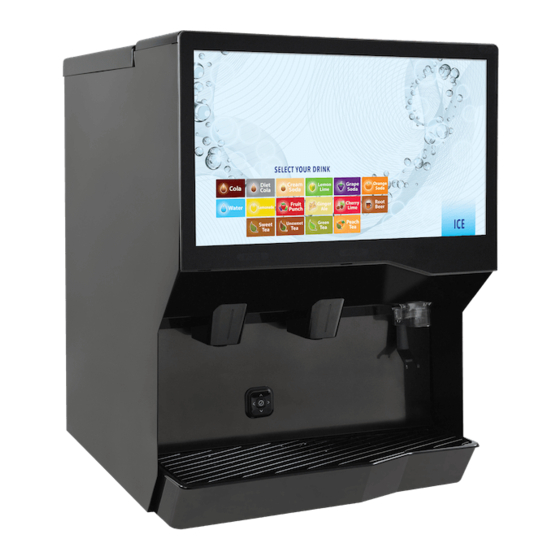
Twin Pour 30
LANCER INSTALLATION GUIDE
Model TP30
Lancer PN:28-3089
Revision: 00-0, 11/18/2020
Advertisement
Table of Contents
Troubleshooting

Related Manuals for lancer Twin Pour 30


Summary of Contents for lancer Twin Pour 30
- Page 1 FOR QUALIFIED INSTALLER ONLY. This basic Installation Sheet is an initial release. If a complete Operations Manual (for the unit being installed) is required or needed, please refer to the Lancer website (lancerworldwide.com) for immediate access, or for your convenience, scan this QR code with a mobile device for immediate access to oth- er Technical Documents and alternative translations (if available) pertaining to this unit.
-
Page 2: Automatic Agitation
F Electrical Warning Check the dispenser name plate label, located behind the splash plate, for the correct electrical requirements of unit. Do not plug into a wall electrical outlet unless the current shown on the serial number plate agrees with local current available. Follow all local electrical codes when making connections. -
Page 3: Specifications And Features
Veuillez lire ce manuel avant d’installer et d’utiliser cet appareil. Pour l’entretien, communiquez avec le service à la clientèle de Lancer ou avec un technicien autorisé. Ayez sous la main le numéro de série et le modèle de distributrice lors de votre appel. -
Page 4: Installation
48 pouces si le point de contact est à moins de 10 pouces Lancer recommande de ne PAS utiliser de glace pilée ou de glace en écailles avec le distributeur. de l’avant du comptoir, ou un maximum de 46 pouces si le point de contact est plus à... -
Page 5: Dispenser Installation
être effectuées par du personnel qualifié disposant de An adapter plate is required when installing an icemaker. connaissances actuelles et cumulant une expérience Contact your Sales Representative or Lancer Customer pratique, conformément à la réglementation en vigueur. Service for more information. - Page 6 If necessary, install water booster (Lancer PN MC-163172) Insert and install carbonator probe. between water supply and the remote pump deck. Using tubing cutters, cut the water line and install U-fitting then route appropriate tubing from the U-fitting to the plain water inlet at the unit.
- Page 7 ! CAUTION 14. Install condensation fan on the underside of the unit by (1) pushing fan bracket into slots in the right wall, then (2) sliding Drain line must be insulated with a closed cell down to engage. insulation. Insulation must cover the entire length of the drain hose, including fittings.
- Page 8 Installing CO Supply Connect tubing routed from the tee at the syrup pumps to the Connect high pressure CO regulator assembly to CO second low pressure regulator. cylinder or bulk system. ! ATTENTION Before installing regulator, ensure that a seal (washer or o-ring) is present in regulator attachment nut.
-
Page 9: Dispenser Setup
Dispenser Setup Turn on the power to the dispenser by pressing the on/off Turn on water source. toggle button on the right side of the unit electrical box and turning the 3-way keyswitch to the vertical position. Open the pressure relief valve located on the front of the unit, by flipping up on the valve cap lever. - Page 10 NOTE REMARQUE The technician’s access to the service menu allows Une fois la purge activée, elle continuera à distribuer access to the following menus: System, Lighting, Sold le produit jusqu’à ce qu’elle soit désactivée. Pour Out, Time & Delays, Valve Configurations, Maintenance, désactiver la purge, appuyez simplement à...
- Page 11 NOTE NOTE Pour vérifier la présence de fuite de CO , fermer la valve Each brand has a default water type and ratio already de la bouteille de CO pour déterminer si la pression du set when they are selected. The water type and ra- système chute dans un délai de cinq minutes.
-
Page 12: Calibration And Maintenance
CALIBRATION & MAINTENANCE Calibrating Plain/Carbonated Water Modules NOTE From the Service menu, tap the Valve Calibration button. Tap the Calibrate on the Water Valve to be calibrated. The larger the volume dispensed, the more accurate the results. REMARQUE Plus le volume distribué est grand, plus les résultats sont précis. - Page 13 Calibrating Brand Syrup Modules - Using a Graduated Cylinder NOTE NOTE Ensure there is ice on the cold plate and the lines are The water flow rate was set to 73.93 ml/sec, which cold before attempting to set the flow rates on the makes the final syrup flow rate 14.79 ml/s.
- Page 14 Calibrating Brand Syrup Modules - Using a Syrup Separator NOTE Using the slider, enter 5 seconds as the dispense time. A syrup separator is included with every machine for use with a Ratio Cup to set the brand module flow rates.
-
Page 15: Time & Delay Features
FEATURES OF THE TWIN POUR 30 DISPENSER Time & Delay Features Sold Out Features From the Service Menu, tap the Time & Delays button to From the Service Menu, tap the Sold Out button. access the Time & Delays Menu. - Page 16 Lancer Worldwide Customer Service 1-800-729- 1500, to register your account. From the Network Status menu, change connection type to “Wired” to enable server connection. Save settings and exit service menu. Use “Dispenser ID” to activate unit on the Lancer Link https://prod-lancercorp-portal-app-cu. website: azurewebsites.net/ NOTE...
-
Page 17: Update Software
Update Software Verify that the correct update is displayed on the screen then tap Start Update. Load the .update file on to any USB formatted to “FAT32” as NOTE shown in the image below. The screen will automatically conduct a power cycle once the update is complete. -
Page 18: Cleaning And Sanitizing
Applicable safety precautions must be observed. Instruction warnings on the product being used must be followed. Renseignements Généraux À sa sortie de l’usine, l’équipement Lancer (qu’il soit nouveau ou remis à neuf) a été nettoyé et aseptisé conformément aux lignes directrices de la NSF. L’exploitant de l’équipement doit en assurer l’entretien continu comme indiqué dans ce manuel ou selon les lignes directrices du ministère de la Santé... -
Page 19: Scheduled Maintenance/Cleaning
! ATTENTION • Portez des gants sanitaires pendant le nettoyage de l’appareil et observez toutes les précautions de sécurité applicables. N’UTILISEZ PAS un nettoyeur à jet d’eau pour nettoyer ou désinfecter l’appareil. • • Afin d’éviter la contamination, NE DÉBRANCHEZ PAS les conduites d’eau pendant le nettoyage et la désinfection des conduites de sirop. -
Page 20: Cleaning & Sanitizing Nozzles
Cleaning & Sanitizing Nozzles REMARQUE Remove the nozzle cover by squeezing sides and pulling Il est recommandé d’effectuer cette procédure une down. fois par mois, ou plus souvent si vous le souhaitez. Remove nozzle by twisting counterclockwise and pulling Utilisez la solution de nettoyage décrit à la page 19. downward. -
Page 21: Cleaning & Sanitizing Syrup Lines - Bag In Box
17. Remove the Agitator bar and Hub from the Ice Bin. 18. Using the Cleaning Solution (page 19) and a clean cloth or soft brush, clean the Ice Chute Assembly, Ice Shroud, Auger, all sides of the Ice Bin, and surface of the aluminum casting. 19. -
Page 22: Troubleshooting
TROUBLESHOOTING Valve, Syrup/Flavor Line Troubleshooting TROUBLE CAUSE REMEDY No product when switch No power to dispenser. Check internal breaker and incoming power. is activated. Malfunctioning power supply. Check voltage to power supply. Check fuses. Malfunctioning PCB board. Replace PCB board. Keyswitch is off or keyswitch harness is Turn keyswitch on and/or reconnect keyswitch disconnected. - Page 23 TROUBLE CAUSE REMEDY Insufficient syrup flow. Insufficient CO pressure to BIB pumps. Adjust CO pressure to BIB pumps to 80 psi (0.552 MPa) (min. 70 psi (0.483 MPa). Do not Shutoff on mounting block not fully open. exceed manufacturer’s recommendations. Foreign debris in syrup flow control.
-
Page 24: Ice Bin/Ice Chute/Carbonator Pump Troubleshooting
TROUBLE CAUSE REMEDY Excessive foaming. No ice in bin. Fill bin with ice and allow coldplate to re-stabilize. Incoming water or syrup temperature too high. Correct prior to dispenser. pressure too high. Adjust CO pressure downward, but not less Water flow rate too high. than 25 psi (0.172 MPa). -
Page 25: Remote Syrup Pump Troubleshooting
Remote Syrup Pump Troubleshooting TROUBLE CAUSE REMEDY BIB pump does not Out of CO , CO not turned on, or low CO Replace CO supply, turn on CO supply, or operate when pressure. adjust CO pressure to 70-80 psi (0.483-0.552 dispensing valve is MPa). -
Page 26: Plumbing Diagram
PLUMBING DIAGRAM Twin Pour 30 Plumbing Diagram LEFT RIGHT NOZZLE NOZZLE A: Ambient Syrup Lines S: Chilled Syrup Lines WIRING DIAGRAMS Twin Pour 30 Wiring Diagram PRIMARY TP-30 VALVE WIRING DIAGRAM MICROBUS 14 valves each side UDC2 TOP COM CABLE... -
Page 27: Unit Wiring Diagram - 115 Volt
Unit Wiring Diagram - 115 Volt ETHERNET AGITATION COUPLER MOTOR ICE DOOR TRIGGER KEYSWITCH HDMI USB B LCD DISPLAY ETHERNET HDMI USB A GPIO POWER POWER INPUT POUR POUR JACK microbus OUTPUT BUTTON BUTTON 16POS J7 J5 24DC 115VAC USB A 3.5A Breaker USB B IBD PCB... - Page 28 TIME MODEL 4900 SW2 SWITCH 2: POSITION DOES NOT 11 SECONDS MATTER 9 SECONDS SW1 SWITCH 1: NOT USED FOR 7 SECONDS MODEL 4900 SW1 SWITCH 2: NOT USED FOR 5 SECONDS MODEL 4900 *= DENOTES DEFAULT LANCER PN: 06-3289/01...
- Page 30 6655 Lancer Boulevard San Antonio, TX 78219 lancerworldwide.com A HOSHIZAKI COMPANY...
Need help?
Do you have a question about the Twin Pour 30 and is the answer not in the manual?
Questions and answers