Table of Contents
Advertisement
IBD Bold 30i
Operation Manual
Model TP30
"Lancer" and "Lancer Worldwide" are registered trademarks of Lancer Corp.
© 2021 by Lancer, all rights reserved.
For more Information visit
lancerworldwide.com
or call Tech Support/Warranty: 800-729-1550
6655 Lancer Boulevard • San Antonio, TX 78219 • custserv@lancerworldwide.com • ©2021 Lancer Worldwide • Lancer PN: 28-3111 • Revision 2/15/2022
Advertisement
Table of Contents

Related Manuals for lancer IBD Bold 30i


Summary of Contents for lancer IBD Bold 30i
- Page 1 “Lancer” and “Lancer Worldwide” are registered trademarks of Lancer Corp. © 2021 by Lancer, all rights reserved. For more Information visit lancerworldwide.com or call Tech Support/Warranty: 800-729-1550 6655 Lancer Boulevard • San Antonio, TX 78219 • custserv@lancerworldwide.com • ©2021 Lancer Worldwide • Lancer PN: 28-3111 • Revision 2/15/2022...
-
Page 2: Table Of Contents
Dispenser Setup ............16 SBC Wiring Diagram ..........43 Access Service Menu ..........16 Plumbing Diagram ........... 44 IBD BOLD 30i SERVICE MENU .......17-31 Valve Wiring Diagram ..........44 Water Purging ............17 Power Supply Wiring Diagram ........ 45 Adding Brand/Flavor Valves ........18 Unit Wiring Diagram .......... -
Page 3: Important Safety Instructions
IMPORTANT SAFETY INSTRUCTIONS READ ALL SAFETY INSTRUCTIONS BEFORE USING THIS UNIT. This manual contains important safety information and all applicable safety precautions must be observed. To reduce the risk of fire, electric shock, damage to the equipment or personal injury when using this unit all instuctions/warnings on the product being used must be followed: ! WARNING ! ATTENTION... -
Page 4: Warning
F Avertissement - Électricité Reportez-vous à l’étiquette d’identification de la distributrice située derrière la plaque antiéclaboussures pour connaître les caractéristiques électriques de l’appareil. Ne branchez pas l’appareil dans une prise électrique murale à moins que le courant disponible corresponde à l’intensité nominale indiquée sur l’étiquette portant le numéro de série. Les raccordements électriques doivent être conformes au code électrique local. -
Page 5: Water Notice
! Water Notice Provide an adequate potable water supply. Water pipe connections and fixtures directly connected to a potable water supply must be sized, installed, and maintained according to federal, state, and local laws. The water supply to the carbonator must be at least a 3/8 inches (9.525 mm) pipe with a minimum of 75 psi (0.516 MPa) line pressure, but not exceeding a maximum of 125 psi (0.862 MPa). -
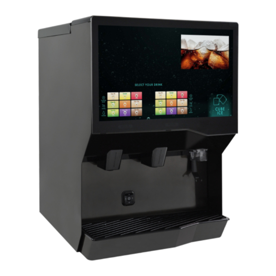
Page 6: Specifications And Features
SPECIFICATIONS AND FEATURES IBD BOLD 30i 40.60 in 30.00 in 34.00 in A. Top Cover B. Touchscreen Display C. Splash Plate D. Cup Rest/Drip Tray DIMENSIONS ELECTRICAL CARBON DIOXIDE (CO ) SUPPLY Width: 30.00 inches (762 mm) 120 VAC / 60 Hz / 5.0 Amps Min Pressure: 70 psi (0.483 MPa) -
Page 7: General Systems Overview-Remote Syrup Pumps
BIB SYSTEM: Is countertop level? Oetiker Clamp Fittings BIB Rack Can the countertop support Water Booster (Lancer PN: the weight of the dispenser? BIB Syrup Boxes 82-3401 or MC-163172 (Include the weight of an ice machine plus weight of ice,... -
Page 8: Installation
Read This Manual This manual was developed by Lancer Worldwide as a reference guide for the owner/operator and installer of this dispenser. Please read this manual before installation and operation of this dispenser. Please see Troubleshooting section for service assistance. If the service cannot be corrected please call your Service Agent or Lancer Customer Service. -
Page 9: Selecting/Preparing A Counter Location
Pour s’assurer que le service de boissons est accessible Unit may be installed directly on countertop or on legs. If à tous les clients, Lancer recommande que la hauteur du installed directly on the counter, unit must be sealed to the comptoir et la sélection de l’équipement soient planifiées... -
Page 10: Installing An Icemaker
An adapter plate is required when installing an icemaker. Contact your Sales Representative or Lancer Customer Service for more information. A bin thermostat is required in order to control the level of ice in the dispenser (Refer to ATTENTION note above). -
Page 11: Dispenser Installation
The installation or relocation must be carried out by qualified personnel with up-to-date knowledge Install water booster (Lancer PN MC-163172) between water and practical experience in accordance with current supply and the remote pump deck. - Page 12 Route appropriate tubing from the syrup pump location to 11. Remove drip tray by lifting up and pulling out. Connect the the syrup inlets and connect tubing to all syrup inlets. insulated drain line to the drain fitting. A. Oetiker Pliers B.
-
Page 13: Condensation Fan Installation
Condensation Fan Installation NOTE Install condensation fan on the underside of the unit by (1) pushing fan bracket into slots in the right wall, then (2) When installing the drip tray, make sure both of the sliding down to engage. cold plate drain hoses are lined up to the openings in the drip tray. -
Page 14: Installing Remote Syrup Pumps-Bag In Box
Installing Remote Syrup Pumps - Bag In Box Install BIB rack and remote pumps according to Install BIB (bag in box) connectors onto the syrup pump manufacturers’ instructions. inlet tubing. Once pumps and BIB rack are installed, measure and ! ATTENTION cut tubing to length between the pump CO inlets, then connect tubing to all pumps. -
Page 15: Installing Co Supply
Installing CO Supply Connect high pressure CO regulator assembly to CO Route appropriate tubing from the low pressure CO cylinder or bulk system. regulator manifold location to the 1/4” nut, 3/8” stem on the high pressure CO regulator attached to source and ! ATTENTION connect tubing. -
Page 16: Dispenser Setup
Hold open until water conque de dommage. Contactez le service à la clientèle flows from the relief valve; then, close (flip down) the relief de Lancer pour obtenir de l’aide. Assurez-vous que valve. la distributrice est reliée à la terre pour éviter des blessures graves ou des décharges électriques. -
Page 17: Ibd Bold 30I Service Menu
IBD BOLD 30i SERVICE MENU Valve Configuration - Water Purging Repeat steps 2 - 3 for the remaining water buttons. Tap Valve Configuration on the navigation menu. Make sure the pump deck is turned OFF before turning on Turn on CO at the source then, using a screwdriver, adjust the high pressure regulator at the source to 110 psi (0.758... -
Page 18: Adding Brand/Flavor Valves
Valve Configuration - Adding Brand/Flavor Valves NOTE In order to use a brand or flavor, the valve must first be Ambient flavor valves (A1-A8) can be configured as configured. ambient brand valves by pressing and holding the Set Tap Valve Configuration on the navigation menu. to Brand or Set to Flavor buttons. -
Page 19: Plain/Carb Water Calibration
Valve Configuration - Plain/Carb Water Calibration NOTE NOTE Ensure there is ice on the cold plate and the lines are The larger the volume dispensed, the more accurate cold before attempting to set the flow rates on the the results. valves. -
Page 20: Graduated Cylinder Syrup Calibration
Valve Configuration - Graduated Cylinder Syrup Calibration Tap Valve Configuration on the navigation menu. With the graduated cylinder placed in a position below the nozzle, tap the Start button. The unit will dispense the Tap on the syrup valve to be calibrated. designated syrup amount. -
Page 21: Ratio Cup Syrup Calibration
Valve Configuration - Ratio Cup Syrup Calibration After calibrating water valves, remove the nozzle cover by Hold the ratio cup under the separator and turn it as squeezing the sides and pulling down. needed for best visibility. Press and hold the Dispense button until cup is filled to target window. -
Page 22: Sold Outs
Valve Configuration - Sold Outs REMARQUE Tap Valve Configuration on the navigation menu. Prêt - signifie qu’il y a un produit disponible et que la Tap the desired valve to adjust operational state. vanne distribuera lorsqu’elle est activée. Out - signifie qu’il n’y a pas de produit disponible ou qu’il y a un problème avec la marque spécifiée et sera distribué... - Page 23 GRID OPTIONS The Selection Grid Type toggles either a Single or Dual Drag and drop brand to desired location. grid for the customer interface. The single grid provides larger icons in a single grouping while the dual grid will automatically center the brand icons above each associated nozzle.
-
Page 24: Digital Merchandising
Background image can be changed using the background Ice image can be changed using the ice image selector image selector pane. To upload new background images, pane. To upload new ice images, refer to the Import USB Data section. refer to Import USB Data section. Press the Default Ice Image to revert back to the original Press the Default Background to revert back to the original ice image. -
Page 25: Load Usb
Data Management - Load USB Drive NOTE For videos, create a .txt file in any editor software (ex: Notepad on Windows machines) that contains the name USB drive must be formatted to “FAT32”. of all video files for a playlist. The name of the text file will be the playlist name. -
Page 26: Import Usb Data
Data Management - Import USB Data Tap Videos button under the Import USB Data pane to Lift screen to access USB ports. import videos and playlists. Insert USB drive into an open USB port on DIO board. Tap the Brands button under the Import USB Data pane to import new brand icons. -
Page 27: Export Usb Data
Ne les utilisez Tap the Valve Configuration button under the Export USB que si le service client de Lancer vous le demande. Data pane to export valve brand mapping data. Tap the Update Software button under the Software pane... -
Page 28: Maintenance
Maintenance Tap the Test Solenoids button to enter the Solenoid Test Tap Maintenance on the navigation menu. Screen. Tap the Screen Lockout button under the Tools pane to enter the touchscreen disable screen. Tap Start Solenoid Test to begin testing of all valves. Tap Press to Disable Touchscreen to disable the screen for general cleaning. -
Page 29: Lancer Link Setup
1-800-729-1500, to register your account. Ethernet Tap Lancer Link on the navigation menu. Once initial assigned by Lancer customer service, use “Dispenser ID” to activate unit on the Lancer Link website: https://prod-lancercorp-portal-app-cu.azurewebsites.net/ NOTE Refer to Lancer Link User Guide (PN: 28-3067) for instructions on Update any parameters under the Network Configuration web-based setup. -
Page 30: Settings
Settings POWER SOFTWARE AND DATA Lock Machine Software and Data Press and hold the Hold to Lock button to lock the Press and hold the Hold to Reset button clear or reset data. dispenser. This option will turn off the screen to the dispenser and not allow any access to the service menu or customer interface until the unlock PIN is entered. - Page 31 Sets the timezone UI software name and version number Set Date and Time Lancer Service Menu Version Manually set the date and time Lancer service menu version number Operating System Version SECURITY Operating system name and version number System Manager Version...
-
Page 32: Cleaning And Sanitizing
General Information GENERAL INFORMATION Lancer equipment is shipped from the factory after being cleaned and sanitized in accordance with the National Sanitation Foundation (NSF) guidelines. The operator of the equipment must provide continuous maintenance as required by this manual and/or state and local health department guidelines to ensure proper operation and sanitation requirements are maintained. -
Page 33: Cleaning And Sanitizing Solutions
Cleaning and Sanitizing Solutions Cleaning Solution Nozzle Sanitizing Solution Mix a mild, non-abrasive detergent (e.g. Sodium Laureth Sulfate, Prepare a chlorine solution (less than pH 7.0) containing 50 dish soap) with clean, potable water at a temperature of 90°F to PPM chlorine with clean, potable water at a temperature of 110°F (32°C to 43°C). -
Page 34: Cleaning And Sanitizing Nozzles
Cleaning and Sanitizing Nozzles Prepare the nozzle sanitizing solution as described on page Using the nozzle brush provided in the installation kit and the cleaning solution described on page 33, clean the outer nozzle of any residual syrup. Remove the nozzle cover by squeezing the sides and pulling down. -
Page 35: Troubleshooting
TROUBLESHOOTING Valve, Syrup/Flavor Line Troubleshooting TROUBLE CAUSE REMEDY No product when switch No power. Replace Single-Board Computer (SBC). is activated. Malfunctioning power supply. Replace SBC. Malfunctioning SBC. Replace SBC. Malfunctioning screen. Replace screen. Key switch is in sleep mode. Turn key switch to on position. Dispenser in sleep mode. - Page 36 TROUBLE CAUSE REMEDY Insufficient water flow Insufficient incoming supply pressure. Verify incoming supply water pressure to plain (plain water drinks). water inlet is a minimum of 75 psi (0.516 MPa) Shutoff on mounting block not fully open. and a maximum of 125 psi (0.862 MPa). Foreign debris in water flow control.
- Page 37 TROUBLE CAUSE REMEDY Excessive foaming. No ice in bin. Fill bin with ice and allow coldplate to restabilize. Incoming water or syrup temperature too high. Correct temperature prior to reaching pressure too high. dispenser. Water flow rate too high. Adjust CO pressure downward, but not less Nozzle and diffuser not clean.
- Page 38 Remote Syrup Pump Troubleshooting TROUBLE CAUSE REMEDY BIB pump does not Out of CO , CO not turned on, or low CO Replace CO supply, turn on CO supply, or operate when pressure. adjust CO pressure to 70-80 psi (0.483-0.552 dispensing valve is MPa).
-
Page 39: Illustrations And Part Listings
ILLUSTRATIONS AND PART LISTINGS Graphics & Labels Assembly Part No. Description 06-2342/01 Electrical Hazard Warning Label 06-3289/01 Dip Switch Legend Label 06-4131 Plumbing Diagram Label 06-2342 06-3289/01 06-4131... -
Page 40: Main Unit Assembly
Main Unit Assembly 05-4280 05-4284 05-4282 30-16845/01 03-0368 10-0918 10-0762 82-4315/01 30-16741/01 05-2845 51-7316/01 2X 20-2000/01 51-7320/01 30-16740/01 4X 51-7318/01 30-16846 6X 19-0262/03 4X 19-1011 91-0198 18X 19-1010 2X 49-1000-01 82-4415 51-7321/01 05-4397/01 52-4253 30-11044 91-4008/01 82-4450 05-0999/01 51-7341/01 05-4285 05-4391 23-2067/02 30-16739/02... - Page 41 Part No. Description 03-0368 RETAINER,PIN,AGITATOR,IBD 05-0999/01 LEVER,CHUTE,IBD 05-2845 INSERT,BIN,THERMORFORM,P-ICE 05-4280 LID,BACK,TP30 05-4282 COVER,FRONT,TP30 05-4284 LID,ICE CHUTE,TP30 05-4285 COVER,NOZZLE,TP30 05-4391 GUARD,VALVE,TP30 05-4397/01 COVER,VALVE PLT,TP30 10-0762 PIN,HEX DESIGN,FS16 10-0918 SHAFT,AGITATOR,P-ICE 19-0262/03 VALVE ASSY,LFCV,0.2 INJ,NAT,SC 19-1010 VALVE ASSY,LFCV,3.0 SYR,BLK,SC 19-1011 VALVE ASSY,LFCV,3.0 SODA,GRY,S 20-2000/01 SPRING,GAS,5.47 STROKE,40 LBS.
-
Page 42: Electrical Assembly
Electrical Assembly 64-6036 52-4328 81-0371/01 52-4258 82-6580 52-4214 52-4329 64-5037/01 52-4272 52-4306 52-4337 52-4324 52-4326/01 Part No. Description Part No. Description 52-4258 POWER SUPPLY,24VDC,65W 52-4214 POWER SUPPLY,27V,120W 52-4272 MICROBUS PCB ASSY 52-4306 KEYSWITCH ASSY,TP30 52-4326/01 HARNESS,MIKROBUS TO KS 52-4324 HARNESS,DIO TO ICE,SWITCHES 52-4329 HARNESS ASSY,VALVE,LEFT 52-4326... -
Page 43: Display Assembly
Display Assembly IBD 30i SHEET METAL BACK PLATE MOUNTED ON TO LCD AND SBC SBC PCB IS LOCATED UNDER THE SHEET METAL COVER SBC COVER, WITH THUMB SCREWS ONLY WAY TO ACCESS THE PCB 82-6725 Display Assembly IBD 30i SBC Wiring Diagram - 115 Volt THIS IS A DUAL USB “A”... -
Page 44: Plumbing Diagram
Bold 30i Plumbing Diagram Bold 30i Valve Wiring Diagram PRIMARY IBD 30i VALVE WIRING DIAGRAM MICROBUS 14 valves each side UDC2 TOP COM CABLE Dip 1,2,3,4, off 4 ambient 8 syrups BOTTOM CONTROLLER TOP CONTROLLER 1 plain water 1 carb water CW2 S13 RIBBON SECONDARY... -
Page 45: Power Supply Wiring Diagram
Power Supply Wiring Diagram - 115 Volt AGITATION MOTOR LCD DISPLAY ICE DOOR SOLENOID BLU/BLK DC FAN Pink 3.5 AMP LINE BREAKER LOAD Pink 24VDC AC IN IBD PCB AC BLOCK 27VDC AC VOLT TO SUPPLY Pink 7Amp 3.5 AMP LINE BREAKER 27VDC BLOCK... -
Page 46: Unit Wiring Diagram
TIME THIS DISPENSER SW2 SWITCH 2: POSITION DOES NOT 11 SECONDS MATTER 9 SECONDS SW1 SWITCH 1: NOT USED FOR 7 SECONDS THIS DISPENSER SW1 SWITCH 2: NOT USED FOR 5 SECONDS THIS DISPENSER *= DENOTES DEFAULT LANCER PN: 06-3289/01... -
Page 47: Counter Cutout
Counter Cutout BOLD COUNTER CUTOUT 30” 15/16” 28 1/8” 23” 18 5/8” 15” 34” 11 1/2” 3“ DIAMETER OPTIONAL 1 1/2” 3“ F R O N T D I S P E N S E R 1 5/8” D R I P T R A Y 9“... - Page 48 6655 Lancer Boulevard San Antonio, TX 78219 lancerworldwide.com A HOSHIZAKI COMPANY...
Need help?
Do you have a question about the IBD Bold 30i and is the answer not in the manual?
Questions and answers