Table of Contents
Advertisement
Quick Links
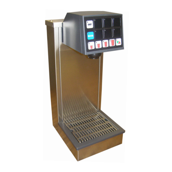
MVU TOWER
Operation Manual
PN: 28-0777/01
Lancer Corp.
6655 Lancer Blvd.
San Antonio, Texas 78219
800-729-1500
Technical Support/Warranty: 800-729-1550
custserv@lancercorp.com
lancercorp.com
Manual PN: 28-0777/01
JULY, 2009
MVU
FOR QUALIFIED INSTALLER ONLY
"Lancer" is the registered trademark of Lancer © 2014 by Lancer, all rights reserved.
Advertisement
Table of Contents

Related Manuals for lancer MVU TOWER


Summary of Contents for lancer MVU TOWER
- Page 1 PN: 28-0777/01 Lancer Corp. 6655 Lancer Blvd. San Antonio, Texas 78219 800-729-1500 Technical Support/Warranty: 800-729-1550 custserv@lancercorp.com lancercorp.com Manual PN: 28-0777/01 JULY, 2009 FOR QUALIFIED INSTALLER ONLY “Lancer” is the registered trademark of Lancer © 2014 by Lancer, all rights reserved.
-
Page 2: Table Of Contents
PORTION CONTROL PROGRAMMING (MVU) (NO TOP-OFF)........14-15 PORTION CONTROL PROGRAMMING WITH TOP-OFF (MVU)........15 SHOT SIZE PROGRAMMING..................16-17 3. RECOMMENDED SERVICE AND MAINTENANCE..............18 SCHEDULED........................18 CLEANING AND SANITIZING SYSTEMS................18 CLEANING AND SANITIZING BAG-IN-BOX (BIB) SYSTEMS...........19 NOZZLES..........................19 4. TROUBLESHOOTING.........................20 5. DISPENSER DISPOSAL......................20 6. ILLUSTRATIONS AND PART LISTINGS..................22 MVU TOWER ASSEMBLY.....................22-23... -
Page 3: Specifications
MVU TOWER SPECIFICATIONS DIMENSIONS FITTINGS PLAIN WATER SUPPLY Width: 7.25 inches (184.15 mm) Plain water inlet: 3/8” barb Min flowing pressure: Depth: 9 inches (228.6 mm) 20 PSI (0.138 MPA) Brand syrup inlets: 3/8” barb Height: 16.5 inches (419 mm) Max flowing pressure: 50 PSI (0.345 MPA) -
Page 4: Pre-Intallation Checklist
PRE-INSTALLATION CHECKLIST BEFORE GETTING STARTED Each unit is tested under operating conditions and is thoroughly inspected before shipment. At the time of shipment, the carrier accepts responsibility for the unit. Upon receiving the unit, carefully inspect the carton for visible damage. If damage exists, have the carrier note the damage on the freight bill and file a claim with carrier. -
Page 5: Warnings/Cautions
WARNING/ADVERTENCIA/AVERTISSEMENT The dispenser is for indoor use only. This unit is not a toy. Children should not be supervised not to play with appliance. It should not be used by children or infirm persons without supervision. This appliance is not intended for use by persons (including children) with reduced physical, sensory or mental capabilities, or lack of experience and knowledge, unless they have been given supervision or instruction concerning use of the appliance by a person responsible for their safety. - Page 6 20 PSIG (0.138 MPA). REGLES DE SECURITE POUR L’NSTALLATION DU DISTRIBUTEUR DE SODAS La proprètè da cet ensamable est assurè à I’usine sulvant les spècifications èmis par Lancer . Il est essentiel de respecter les 6 points suivants pour l’installation de l’appareil: 1.
- Page 7 ELECTRICAL WARNING/ADVERTENCIA ELÉCTRICA/ AVERTISSEMENT ÉLECTRIQUE Check the dispenser serial number plate for correct electrical requirements of unit. Do not plug into a wall electrical outlet unless the current shown on the serial number plate agrees with local current available. Follow all local electrical codes when making connections.
- Page 8 WATER NOTICE/AGUA AVISO/ PRÉAVIS DE L’EAU Provide an adequate potable water supply. Water pipe connections and fixtures directly connected to a potable water supply must be sized, installed, and maintained according to federal, state, and local laws. The water sup- ply line must be at least a 3/8 inches (9.525 mm) pipe with a minimum of 20 PSI (0.138 MPA) line pressure, but not exceeding a maximum of 50 PSI (0.345 MPA).
-
Page 9: Installation
1. INSTALLATION UNPACKING A. The Lancer dispenser is shipped in a corrugated shipping carton. B. Remove dispenser from corrugated shipping carton. C. Inspect unit and parts for concealed damage. If damage exists, notify delivering carrier and file claim against same. -
Page 10: Connection Of The Unit
CONNECTION OF THE UNIT A. Position the CO2 gas tank in the desired location. Assemble high pressure regulator to CO2 gas tank and run jumper line to low pressure regulator. B. Attach the CO2 gas line to the carbonator by attaching the line from the high pressure regulator to the single check valve marked “gas”... -
Page 11: Mvu Operation
2. MVU OPERATION PROGRAMMING THE MVU: Set the MVU buttons as Carbonated, Non-Carbonated, or Flavor Shot Only. The MVU can be programmed to serve soda or plain water beverages as well as a flavor shot from each of the beverage positions on the valve. To enter the programming mode on the MVU and assign water type to each individual brand A. -
Page 12: Set Mvu For Flavor Shots
SET MVU FOR FLAVOR SHOTS A. Press both A and C brand buttons (at the same time) on the MVU panel for five seconds to get into programming mode. B. Press the “Shot” button. 1. The “Shot” button will illuminate. 2. -
Page 13: Flow Rate Check
FLOW RATE CHECK The Dispenser’s water flow rate can be checked/calibrated using the on board computer as a timer. To check/adjust flow rate: A. Remove splashguard and module cover to expose flow controls and solenoids. 1. All active brands should have their shutoffs in the open position as illustrated below. CW = Carbonated Water (sparkling) PW = Plain Water (still) B. -
Page 14: Ratio Process
RATIO PROCESS A. Remove outer nozzle and insert MVU separator if not done on previous step. B. Prime separator by running the valve. C. Press and fill the ratio cup to the appropriate levels. D. Check/adjust ratio on each brand. 1. -
Page 15: Portion Control Programming With Top-Off (Mvu)
C. Fill cup 1/3 full with ice and place under the nozzle, push and hold a drink “size” button until the cup is full. 1. Once the pour is completed, the LED will blink slowly to indicate that a new pour duration has been programmed for that key. -
Page 16: Shot Size Programming
SHOT SIZE PROGRAMMING Flavor shot portions can be adjusted using the MVU touchpad and a graduated cylinder. To adjust flavor shots: A. While in Portion Control Programming, press the Shot button. 1. Pressing the Shot button again will exit Shot Size Programming. - Page 17 SHOT SIZE PROGRAMMING (CONTINUED) DISPENSER OPERATION Crew Serve Beverage Dispensing Flavor Shot Dispensing - Portion Control A. Place cup under MVU nozzle. B. Press the “Shot” button. 1. The “Shot” LCD will stay illuminated (active) for 10 seconds. C. Select Brand Button. 1.
-
Page 18: Recommended Service And Maintenance
CLEANING AND SANITIZING SYSTEMS A. General Information 1. Lancer equipment (new or reconditioned) is shipped from the factory cleaned and sanitized according to NSF guidelines. The operator of the equipment must provide continuous maintenance as required by this manual and state and local health department guidelines to maintain proper operation and sanitization. -
Page 19: Cleaning And Sanitizing Bag-In-Box (Bib) Systems
CLEANING AND SANITIZING BAG-IN-BOX (BIB) SYSTEMS A. Disconnect syrup quick disconnect coupling from syrup packages and connect coupling to a bag valve removed from an empty Bag-in-Box package. B. Place end of syrup inlet line, with bag valve attached, in a clean container filled with clean, potable, roomtemperature water. -
Page 20: Troubleshooting
4. TROUBLESHOOTING TROUBLE CAUSE REMEDY 4.1 No carbonation. A. Carbonator motor not running. A. Check power supply. Be sure toggle switch is in ON position. B. Absence of CO2 gas. B. Replace with full tank of CO2 gas. C. Gas only from valves. C. - Page 21 NOTES...
-
Page 22: Illustrations And Part Listings
6. ILLUSTRATIONS AND PARTS LISTINGS MVU TOWER ASSEMBLY... - Page 23 MVU TOWER ASSEMBLY (CONTINUED) Item Part No. Description Item Part No. Description 51-6311 Structure, MVU 54-0464 Cover Assy, MVU 30-1649/01 Plate, Splash 52-3160 Panel Assy, ID 30-10431 Plate, Faucet 04-0236 Scr, 10-24x.375 30-1648 Cap, Tower, 1&2 04-0470 Scr, 6-19x.500 05-0953...
- Page 24 Lancer Corp. 800-729-1500 Technical Support/Warranty: 800-729-1550 custserv@lancercorp.com lancercorp.com...
Need help?
Do you have a question about the MVU TOWER and is the answer not in the manual?
Questions and answers