
Related Manuals for Renishaw VIONiC REXM20


Summary of Contents for Renishaw VIONiC REXM20
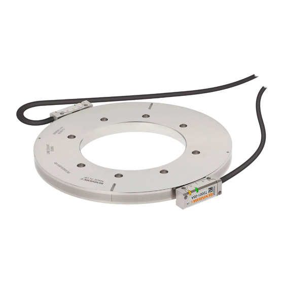
- Page 1 Installation guide M-6195-9239-03-D VIONiC REXM20 / REXT20 ultra-high accuracy angle encoder system ™...
-
Page 2: Table Of Contents
REXM20/REXT20 installation Ring orientation for partial arc applications VIONiC encoder system quick-start guide Readhead mounting and alignment System calibration Restoring factory defaults Enabling/disabling AGC Output signals Speed Electrical connections Output specifications General specifications Ring technical specifications VIONiC REXM20/REXT20 installation guide... -
Page 3: Legal Notices
Renishaw office. Renishaw warrants its equipment and software for a limited period (as set out in the Standard Terms and Conditions), provided that they are installed and used exactly as defined in associated Renishaw documentation. - Page 4 WEEE recycling guidelines The use of this symbol on Renishaw products and/or accompanying documentation indicates that the product should not be mixed with general household waste upon disposal. It is the responsibility of the end user to dispose of this product at a designated collection point for waste electrical and electronic equipment (WEEE) to enable reuse or recycling.
-
Page 5: Storage And Handling
+70 °C −20 °C Ring and readhead Ring only Readhead only Acetone Acetone N-heptane 95% relative humidity (non-condensing) to IEC 60068‑2‑78 Operating Chlorinated Chlorinated COCH COCH Solvents Solvents +70 °C 0 °C Propan-2-ol Methylated Methylated CHOHCH Spirits Spirits VIONiC REXM20/REXT20 installation guide... -
Page 6: Vionic Readhead Installation Drawing
NOTES: Ring centreline refers to the centre of the ring based on the full thickness, i.e., including the raised flat portion. External magnetic fields greater than 6 mT, in the vicinity of the readhead, may cause false activation of the limit and reference sensors. VIONiC REXM20/REXT20 installation guide... -
Page 7: Rexm20/Rext20 Installation Drawing
350.3 – 350.5 22.5° 65 536 417.0 – 417.4 22.5° *52 mm and 57 mm rings have dimple fiducial features and no slots. Fiducial marks, 4 positions, to N holes Ø6 aid installation through equispaced Section A-A VIONiC REXM20/REXT20 installation guide... -
Page 8: Rexm20/Rext20 Installation
× 10 deep ‘mid point’ of the run-out. Continue this process until the run-out of the ring is approximately 30 µm (0.0012 inches). Ø 0.2 For dimensions D1, D2, D3, D4 and number of holes N, refer to page VIONiC REXM20/REXT20 installation guide... - Page 9 If the ring has moved position outside the 10 µm limit the screws must be loosened and the ring adjusted. ‘Slot’ fiducial Step 4 Now adjust the ring position until the DTI reading at these points agrees to 10 µm. ‘Dimple’ fiducial ‘Dimple’ fiducial VIONiC REXM20/REXT20 installation guide...
-
Page 10: Ring Orientation For Partial Arc Applications
The ring will now be rotated clockwise so that H1 will see R1 and H2 will see R2, at this point the DSI will become initialised (Figure 1(b)). Figure 1: Small angular movements Figure 2: Large angular movements VIONiC REXM20/REXT20 installation guide... -
Page 11: Vionic Encoder System Quick-Start Guide
12). Repeat the installation and calibration routine. For more details refer to the Advanced Diagnostic Tool ADTi-100 and ADT View software quick-start guide (Renishaw part no. M-6195-9321) and Advanced Diagnostic Tool ADTi-100 and ADT View software user guide (Renishaw part no. M-6195-9413). -
Page 12: Readhead Mounting And Alignment
Optical centreline IN-TRAC ™ reference mark is integrated in the scale, radially aligned with the centre of the mounting hole to the left of the ‘Renishaw’ logo within ±0.5 mm. No external actuator or physical adjustment is required. Rideheight REXT20 2.1 ±0.15 mm The second reference mark is 180°... -
Page 13: System Calibration
0 V for < 3 seconds. The LED will then stop flashing. Settings stored Blue single flashing None, restore factory defaults and recalibrate Blue double flashing Incremental only Blue (auto-complete) Incremental and reference mark VIONiC REXM20/REXT20 installation guide... -
Page 14: Restoring Factory Defaults
The AGC is switched on once the system has been calibrated indicated by a Blue LED. AGC can be manually switched off by connecting the ‘Remote CAL’ output pin to 0 V for > 3 seconds < 10 seconds. The LED will then be solid Green. VIONiC REXM20/REXT20 installation guide... -
Page 15: Output Signals
Remote CAL line must be connected for use with ADTi-100. † 12-way circular Binder mating socket – A-6195-0105. ‡ Pack of 5 14-way JST SH mating sockets: A‑9417‑0025 – Bottom mount; A-9417-0026 – Side mount. Maximum of 20 insertion cycles for JST connector. VIONiC REXM20/REXT20 installation guide... -
Page 16: Speed
Angular speed depends on ring diameter – use the following equation to convert to rev/min. V × 1000 × 60 Angular speed (rev/min) = Where V = maximum linear speed (m/s) and π D = external diameter of REXM20/REXT20 (mm). VIONiC REXM20/REXT20 installation guide... -
Page 17: Electrical Connections
Maximum readhead cable length: 3 m Maximum extension cable length: Dependent on cable type, readhead cable length and clock speed. Contact your local Renishaw representative for more information. NOTE: The maximum cable length between the readhead and the ADTi‑100 is 3 m. -
Page 18: Output Specifications
Synchronised pulse Z, period is available. duration as resolution. † Bi-directionally repeatable. Contact your local Renishaw representative for more information. Limits Open collector output, asynchronous pulse (Not available with ‘A’ cable termination) Active high Repeatability < 0.1 mm... -
Page 19: General Specifications
* Extension cables available. Contact your local Renishaw representative for further details. CAUTION: Renishaw encoder systems have been designed to the relevant EMC standards, but must be correctly integrated to achieve EMC compliance. In particular, attention to shielding arrangements is essential. - Page 20 Gloucestershire GL12 8JR United Kingdom www.renishaw.com For worldwide contact details, please visit www.renishaw.com /contact *M-6195-9239-03* Part no.: M-6195-9239-03-D Renishaw plc. Registered in England and Wales. Company no: 1106260. Issued: 03.2021 Registered office: New Mills, Wotton‑under‑Edge, Gloucestershire, GL12 8JR, UK.
Need help?
Do you have a question about the VIONiC REXM20 and is the answer not in the manual?
Questions and answers