
Related Manuals for Renishaw RCLC


Summary of Contents for Renishaw RCLC
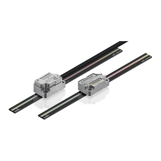
- Page 1 Installation guide M-9414-9913-01-A ATOM DX and RCLC linear encoder system ™ www.renishaw.com/atomdxdownloads #renishaw...
- Page 2 This page is intentionally left blank. ATOM DX and RCLC linear encoder system ™...
-
Page 3: Table Of Contents
RCLC scale specifications ......................40 www.renishaw.com... -
Page 4: Legal Notices
™ encoder systems and similar products are the subjects of one Renishaw plc hereby declares that the ATOM DX encoder system is in compliance with the or more of the following patents and patent applications: essential requirements and other relevant provisions of: •... - Page 5 47 CFR § 2.1077 Compliance Information Further information Unique Identifier: ATOM DX Further information relating to the ATOM DX encoder range can be found in the ATOM DX ™ miniature encoder system data sheet (Renishaw part no. L-9517-9736), Advanced Diagnostic Responsible Party - U.S.
- Page 6 Disposal of waste electrical and electronic equipment The use of this symbol on Renishaw products and/or accompanying documentation indicates that the product should not be mixed with general household waste upon disposal. It is the responsibility of the end user to dispose of this product at a designated collection point for waste electrical and electronic equipment (WEEE) to enable reuse or recycling.
- Page 7 ATOM DX software notices Third party licences The ATOM DX product includes embedded software (firmware) to which the following notices apply: Copyright © 2009 - 2013 ARM LIMITED Copyright © NXP Semiconductors, 2012 All rights reserved. All rights reserved. This Redistribution and use in source and binary forms, with or without modification, are...
- Page 8 Renishaw and the United States Government, civilian federal agency or prime contractor respectively. Please consult the applicable contract or subcontract and the software licence incorporated therein, if applicable, to determine your exact rights regarding use, reproduction and/or disclosure.
-
Page 9: Storage And Handling
Storage and handling WARNING: Do not bend System N-heptane Propan-2-ol CHOHCH www.renishaw.com... - Page 10 Temperature Humidity 95% relative humidity (non-condensing) to IEC 60068-2-78 Storage System −20 °C to +70 °C Operating System 0 °C to +70 °C ATOM DX and RCLC linear encoder system ™...
-
Page 11: Atom Dx System Installation Overview
For information on designing the readhead and scale into the system refer to the detailed installation drawings and 3D models at or contact your local Renishaw representative. For information on the ATOM DX product range refer to the ATOM DX miniature encoder system data sheet (Renishaw part no. L-9517-9736). -
Page 12: Rclc Glass Spar Installation Drawing
2.5 ±0.04 (20 μm version) Operating rideheight: 2.5 ±0.11 (40 μm version) NOTE: ATOM DX cabled readhead variant shown. 2.5 ±0.055 (20 μm version) Overall length L (mm) The epoxy can be applied on one or both sides of the scale. -
Page 13: Equipment Required To Ledge Or Dowel Mount The Rclc Scale
An appropriate length of RCLC scale (see ‘RCLC glass spar installation drawing’ on page 12) • Appropriate cleaning solvents (see ‘Storage and handling’ on page 9) • RGG-2 two part epoxy adhesive (A-9531-0342) Optional parts: • Renishaw scale wipes (A-9523-4040) • Lint-free cloth www.renishaw.com... -
Page 14: Rclc Scale Application (Ledge Or Dowel Mounting)
See ‘RCLC glass spar installation drawing’ page 12 for details. If the dowels or the ledge are permanent, their maximum height above the substrate should not exceed 1.2 mm. ATOM DX and RCLC linear encoder system ™... - Page 15 NOTE: The datum clamp does not need to be positioned adjacent to a reference mark. It can be positioned anywhere along the axis depending upon the customers’ requirements. 6. Clean the scale using Renishaw scale wipes or a clean, dry, lint-free cloth. 7. Remove the temporary dowels (if fitted).
-
Page 16: System Connection: Top Exit Readhead
A-9414-1238 • Provide appropriate strain relief at the readhead. The Renishaw top exit cables are fitted with a P-clip to ensure appropriate cable strain relief. • When using Renishaw’s top exit cables ensure that the P-clip is mounted within a 50 mm radius of the readhead cable exit. - Page 17 Top exit readhead (with readhead cable inserted) Dimensions and tolerances in mm Detail A: Connector (readhead end) and P-clip P-clip Detail B: P-clip dimensions Use M2 tapping drill (∅1.6) as clearance for pin 11.07 5.7 ±0.05 2.09 Hole for M2 screw ∅1.5 ±0.05 www.renishaw.com...
-
Page 18: Readhead Mounting And Alignment: Methods
There is a range of tools available to assist with readhead installation depending upon the system design and these are detailed below. For more details on designing the mounting bracket and selecting the appropriate mounting tools contact your local Renishaw representative. - Page 19 Shims of a known thickness are inserted between the mounting face of the readhead and the bracket to give the correct rideheight of 2.5 mm (±0.2 mm). A-9401-0045 A-9401-0046 A-9401-0047 • Hex key • ATOM DX readhead Optional parts • DTI adaptor (A-9401-0105) www.renishaw.com...
- Page 20 100 µm a single shim should be used; for distances greater than 100 µm select one thick (≥ 100 µm) and one thin (< 100 µm) shim. Care must be taken to ensure the scale surface is not scratched. Renishaw offer a DTI In the above example of a required shim thickness of 130 µm this could either be: adapter that can be used to assist with this process.
- Page 21 ‘nose’ that is machined to the optimum rideheight (2.5 mm ±0.02 mm). It is mounted in place of the readhead directly onto the bracket. The bracket should have location pins or a shoulder to control readhead yaw. Contact your local Renishaw representative for more Shoulder information on bracket design.
- Page 22 6. Install the ATOM DX readhead in place of the dummy head using 2 M2 × 6 screws in diagonally opposite fixing holes. Ensure the readhead is pushed back against the shoulder of the bracket or the mounting face. ATOM DX and RCLC linear encoder system ™...
- Page 23 5. Connect the readhead to the receiving electronics and power-up. 6. Check the readhead set-up LED is flashing green along the full axis of travel. 7. Proceed with ‘System calibration’ on page 25. For more information on bracket design contact your local Renishaw representative. www.renishaw.com...
-
Page 24: Atom Dx Calibration Overview
For more details refer to the Advanced Diagnostic Tool ADTi-100 and ADT View software User guide (Renishaw part no. M-6195-9413) and Advanced Diagnostic Tool ADTi-100 and ADT View software Quick-start guide (Renishaw part no. M-6195-9321). -
Page 25: System Calibration
Reference mark phasing NOTE: The functions described below can also be carried out by using the optional ADTi-100 and ADT View software. See www.renishaw.com/adt for more information. 1. Move the readhead back and forth over the reference mark until the LED stops flashing and remains solid blue. -
Page 26: Restoring Factory Defaults
LED). AGC can be manually switched off by connecting the ‘Remote CAL’ output pin to 0 V for > 3 seconds < 10 seconds. The readhead set-up LED will then be solid green. NOTE: AGC can be switched on or off using the optional ADTi-100 and ADT View software. See www.renishaw.com/adt for more information. ATOM DX and RCLC linear encoder system ™... -
Page 27: Readhead Led Diagnostics
AGC on; optimum set-up Green AGC off; optimum set-up Poor set-up; signal may be too low for reliable operation Blank flash Reference mark detected (visible indication at speed < 100 mm/s only) Alarm 4 red flashes Low signal or over signal; system in error www.renishaw.com... -
Page 28: Troubleshooting
Check that the readhead variant is the correct type for the chosen scale (see the ATOM DX ™ miniature encoder system data sheet (Renishaw part no. L-9517- 9736) for details of readhead configuration) Unable to get a flashing Green LED over System run-out is not within specification •... - Page 29 Check the readhead optical window and scale are clean and free from contamination • Check that the readhead variant is the correct type for the chosen scale (see the ATOM DX ™ miniature encoder system data sheet (Renishaw part no. L-9517-9736) for details of readhead configuration) No reference mark output •...
-
Page 30: Atom Dx Cabled Readhead Dimensions
ATOM DX cabled readhead dimensions Dimensions and tolerances in mm 1.4 (40 μm version) 1.9 (20 μm version) Set-up LED Readhead datum faces 6.45 10.25 12.7 11.7 4.85 Mounting/ datum face 4.15 Ø9 maximum Readhead/ scale orientation 16.5 3 mounting holes Ø2.5 minimum through 20.5... -
Page 31: Atom Dx Top Exit Readhead Dimensions
ATOM DX top exit readhead dimensions Dimensions and tolerances in mm 1.4 (40 μm version) 1.9 (20 μm version) Set-up LED 6.45 10.45 Readhead datum faces 10.25 8.37 12.7 4.85 Mounting/ datum face 4.15 Ø9 maximum Readhead /scale orientation 16.5 3 mounting holes Ø2.5 minimum through... -
Page 32: Bracket Dimensions
‘L’ mounting bracket (A-9402-0037) Side mount bracket (A-9401-0103) 10.5 16.25 3 holes M2 × 0.4 Ø9.15 8.85 12.7 Ø9.4 4.85 3 holes M2 × 0.4 8.25 16.5 16.5 3.25 2 holes M3 × 0.5 ATOM DX and RCLC linear encoder system ™... -
Page 33: Output Signals
NOTE: Top exit cables are terminated with the ‘K’ pin-out or the ‘D’ pin-out dependent upon which top exit readhead cable is used. PCB mount mating connectors: Top entry (BM10B-SRSS-TB); Side entry (SM10B-SRSS-TB). Connector on top exit readhead only: Mating connector (10SUR - 32S). Remote CAL line must be connected for use with the ADTi-100. www.renishaw.com... -
Page 34: Speed
Speed 20 μm ATOM DX readhead Maximum speed (m/s) Clocked Minimum edge Readhead type output option separation (MHz) (ns) (5 µm) (1 µm) (0.5 µm) (0.2 µm) (0.1 µm) (50 nm) (40 nm) (20 nm) (10 nm) (5 nm) (2.5 nm) 7.25... - Page 35 40 μm ATOM DX readhead Maximum speed (m/s) Clocked Minimum edge Readhead type output option separation (MHz) (ns) (10 µm) (5 µm) (2 µm) (1 µm) (0.5 µm) (0.2 µm) (0.1 µm) (50 nm) (40 nm) (20 nm) (10 nm) (5 nm) 18.13...
-
Page 36: Electrical Connections
NOTE: For Renishaw top exit readhead cables the shield connection is provided by the P-clip. Maximum readhead cable length: 3 m Maximum extension cable length: Dependent on cable type, readhead cable length and clock speed. Contact your local Renishaw representative for more information. ATOM DX and RCLC linear encoder system ™... - Page 37 120R Cable Z = 120R A B Z− 220 pF Standard RS422A line receiver circuitry. The capacitors are recommended for improved noise immunity. Single-ended alarm signal termination (Not available with ‘A’ cable termination) Customer Readhead electronics 100R E− 100nF www.renishaw.com...
-
Page 38: Output Specifications
Differentially transmitted signals forced open circuit for > 15 ms when alarm conditions valid. Synchronised pulse Z, duration as resolution. Bi-directionally repeatable. For clarity, the inverse signals are not shown. 40 μm ATOM DX readheads only. 20 μm ATOM DX readheads only. Only the calibrated reference mark is bi-directionally repeatable. ATOM DX and RCLC linear encoder system ™... -
Page 39: General Specifications
Typical sub-divisional error (SDE) 20 μm version < ±75 nm 40 μm version < ±120 nm CAUTION: Renishaw encoder systems have been designed to the relevant EMC standards, but must be correctly integrated to achieve EMC compliance. In particular, attention to shielding arrangements is essential. www.renishaw.com... -
Page 40: Rclc Scale Specifications
12) Accuracy (at 20 °C) ±3 μm Coefficient of thermal expansion (at 20 °C) ~8 μm/m/°C Available lengths (mm) 10, 18, 30, 55, 80, 100, 105 and 130 Mass 13.9 g/m ATOM DX and RCLC linear encoder system ™... - Page 41 +44 (0) 1453 524524 uk@renishaw.com © 2017-2024 Renishaw plc. All rights reserved. This document may not be copied or reproduced in whole or in part, or transferred to any other WHILE CONSIDERABLE EFFORT WAS MADE TO VERIFY THE ACCURACY OF THIS media or language by any means, without the prior written permission of Renishaw.
Need help?
Do you have a question about the RCLC and is the answer not in the manual?
Questions and answers