Table of Contents
Advertisement
Advertisement
Table of Contents

Related Manuals for Renishaw RGH41


Summary of Contents for Renishaw RGH41
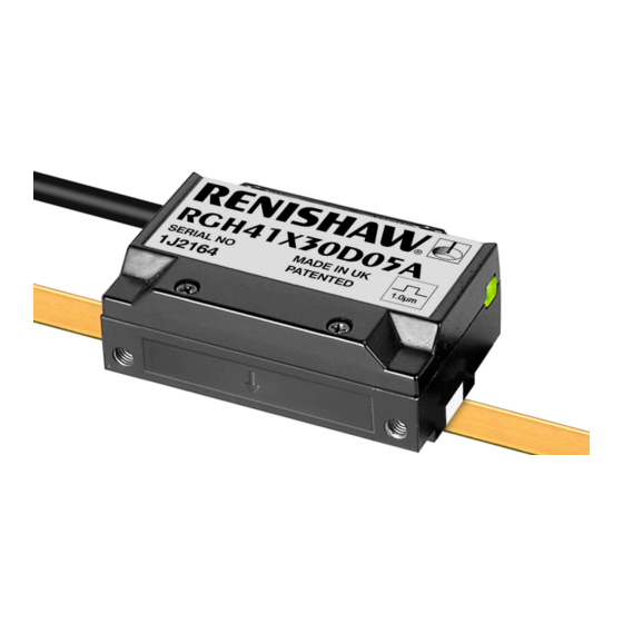
- Page 1 Installation guide M-9537-9016-01-A RGH41 RGS40 linear encoder system...
-
Page 2: Table Of Contents
Contents Product compliance Storage and handling RGH41 readhead installation drawing RGS40 scale installation drawing Scale application End clamps Reference mark and limit switch installation Readhead mounting and alignment Reference mark set-up Limit switch Output signals Speed Electrical connections Output specifications... -
Page 3: Product Compliance
Recyclable received, including interference that may cause undesired operation. Cardboard Not applicable Recyclable The user is cautioned that any changes or modifications not expressly approved by Renishaw plc or Bags High Density Polyethylene Bag HDPE Recyclable authorised representative could void the user’s authority to operate the equipment. -
Page 4: Storage And Handling
Storage Operating Humidity System System 95% relative humidity +70 °C +55 °C (non-condensing) to EN 60068-2-78 -20 °C 0 °C N-heptane Propan-2-ol Acetone Chlorinated Methylated CHOHCH COCH Solvents Spirits RGH41 RGS40 installation guide... -
Page 5: Rgh41 Readhead Installation Drawing
RGH41 readhead installation drawing Dimensions and tolerances in mm Reference mark sensor position R>50 Dynamic bend radius R>10 Static bend radius Optical centre 6 min 12.6 Reference mark actuator ‡ 2 mounting holes M3 x 9.5 deep Epoxy mounted (A-9531-0250) (Yaw tol. -
Page 6: Rgs40 Scale Installation Drawing
Reference mark sensor position (inside readhead) NOTE: The surface roughness of the scale mounting surface must be ≤3.2 Ra. The parallelism of the scale surface to the axis of motion (readhead rideheight variation) must be within 0.05 mm. RGH41 RGS40 installation guide... -
Page 7: Scale Application
The RGA22G scale applicator (A-9531-0239) is designed specifically for installing RGS40-S scale for START use with the RGH41 readhead. When installing RGS40-P scale use scale applicator (A-9531-3528). Allow scale to acclimatize to installation environment prior to installation. Remove applicator and, if necessary, adhere the remaining scale manually. Apply firm finger Mark out ‘START’... -
Page 8: End Clamps
Allow 24 hours at 20 °C Dual limit switches Remove the backing tape from either side. for full cure. Some versions of the RGH41 (options 05 and 06) are configured to detect dual limit switch actuators. End clamp Scale End clamp... -
Page 9: Readhead Mounting And Alignment
Green set-up LED. 0.25 seconds. If it flashes Orange or goes blank, the reference mark adjuster screw An external set-up signal (X or V ) is also available on RGH41 readheads for use where should be turned anti-clockwise by turn and the LED is not visible. -
Page 10: Output Signals
RGH41A, B 1 Vpp analogue Reference mark uni-directional operation 15 way D-type 12 way circular 16 way in-line 12 way circular The RGH41 reference mark output is repeatable for one direction of travel only. Function Signal Colour plug coupling connector... -
Page 11: Speed
Output signals Speed (continued) RGH41 T, D, G, X, N, W, Y, H RS422A digital Digital readheads Non-clocked output readheads 16 way in-line 15 way D-type plug Function Signal Colour connector Maximum speed Lowest recommended counter input frequency Head type... -
Page 12: Electrical Connections
0 V and earth, which could cause electrical noise issues. Recommended signal terminations Digital output - RGH41 T, D, G, X, N, W, Y, H Analogue output - RGH41 A, B Limit termination 5 V to 24 V †... -
Page 13: Output Specifications
Inverse signal not shown for clarity 5 (nom) is a duty cycle, 20 µm duration. Time spent at 5 V increases with Voltage at V signal level. At >70% signal level V is nominal 5 V. signal level 70% 100% RGH41 RGS40 installation guide... -
Page 14: General Specification
-10 °C to +120 °C. Minimum installation 10 °C Renishaw encoder systems have been designed to the relevant EMC standards, but must be Storage -20 °C to +70 °C. correctly integrated to achieve EMC compliance. In particular, attention to shielding... - Page 15 RENISHAW ® and the probe symbol used in the RENISHAW logo are registered trade marks of Renishaw plc in the United Kingdom and other countries. *M-9537-9016-01* apply innovation and names and designations of other Renishaw products and technologies are trade marks of Renishaw plc or its subsidiaries.
Need help?
Do you have a question about the RGH41 and is the answer not in the manual?
Questions and answers