
Related Manuals for Proceq PROFOMETER PM-6


Summary of Contents for Proceq PROFOMETER PM-6
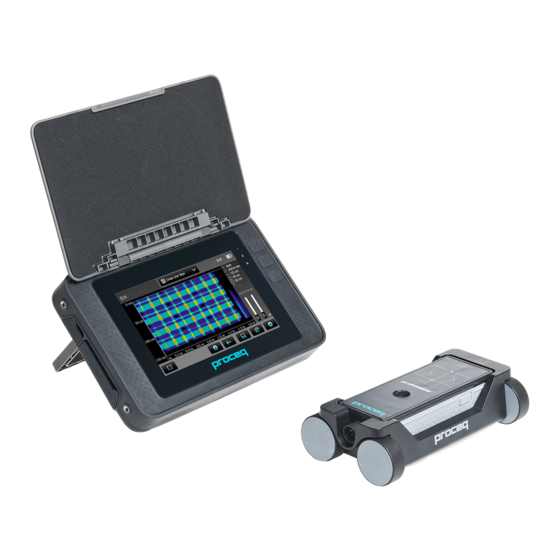
- Page 1 PROFOMETER PM-6 ® OPERATING INSTRUCTIONS 60 Years of Innovation 60 Years of Innovation Made in Switzerland Made in Switzerland...
- Page 2 Scope of Delivery Profometer Touchscreen Unit Battery complete Universal Probe with Cart Profometer PM-6 probe Cable 1.5 m Power Supply with cable (USA, UK or EU) USB Cable 1.8 m (6 ft) DVD with Software Documentation Carrying Strap complete © 2014 Proceq SA...
- Page 3 Overview Press to power on. To power off press again and tap “X Off” on the screen. Soft Key – Switches in and out of full screen view. Back Button – Returns to previous screen. © 2014 Proceq SA...
- Page 4 By pushing simultane- probe along the rebar axis until MC LED ously the cursor jumps to the next line lights up. Then the MC is (in Multi-Line, Area-Scan and Cross-Line precisely above a rebar axis. Mode only) © 2014 Proceq SA...
-
Page 5: Table Of Contents
Standard Warranty and Extended Warranty ....30 Measuring Principle ............. 7 Disposal ................30 Measuring Principle ............7 PM-Link Software ............30 Calibrated Measuring with Profometer PM-6 ....7 Starting PM-Link .............30 The Measuring Range..........7 Adjusting Settings ............32 Resolution ................8 Exporting Data ..............33 Sphere of influence by Ferromagnetic Material ....8... -
Page 6: Safety And Liability
This manual contains important information on the safety, use and main- equipment. tenance of the Profometer PM-6. Read through the manual carefully be- fore the first use of the instrument. Keep the manual in a safe place for • Carry out the stipulated maintenance properly and at the correct time. -
Page 7: Measuring Principle
Measuring Principle Calibrated Measuring with Profometer PM-6 The Profometer PM-6 is calibrated to measure on a normal rebar ar- Measuring Principle rangement; which is an arrangement of non-stainless steel rebars fas- tened with binding wires only e. g. when measuring on welded mesh The Profometer PM-6 uses electromagnetic pulse induction technology wires the cover and diameter readings must be corrected (see “3.7 Prac-... -
Page 8: Resolution
NOTE! This effect can be reduced by the neighboring bar There is a limit to the minimum spacing of bars depending on the cover corretion implemented in the Profometer PM-6. depth and rebar diameter. It is impossible to distinguish between indi- vidual bars above these limits. -
Page 9: Main Menu
Off: Power off. Neighboring Rebar Correction Spacing for Scan-X / Scan-Y 1) 2) It mitigates the influence of neighboring rebars. By setting the spacing to the rebars running parallel to the rebar on which the measurement © 2014 Proceq SA... - Page 10 NOTE! This feature should only be set, if the rebars are running the same surface to get the same color range for comparison purpose. parallel to the Start line (X- or Y-line). It is not activated during the measurements (activated only when storing the data). © 2014 Proceq SA...
-
Page 11: Measurement Screen
Measurement Mode: Select the type of measurement to be carried In the Modes/Views “Zoom to fit” does not show all the details out (see “3.5 Measurement Modes and Storage of Data”). for scanning distance > 10/30 meters (> 32.8/98.4 feet). © 2014 Proceq SA... -
Page 12: Measurement Modes And Storage Of Data
Then scan perpendicular to the CL until the probe tangular mesh (e. g. vertical and horizontal rebars in a wall). cart crosses a rebar. The display shows (only if probe is fixed on the cart): © 2014 Proceq SA... - Page 13 After having located the first layer rebars continue with locating the sec- ond layer rebars. • Position the MC at the mid line of the first layer rebars, e. g. on a column hold the probe with the CL running vertically and move © 2014 Proceq SA...
- Page 14 The cover curve is shown (if selected) within the cover ranges indicated in Figure 2 but a rebar (2.00 to 5.20 inch), set the respective Neighboring Rebar Correction will only be shown up to 90 % of those limits. value first (see Figure 26). © 2014 Proceq SA...
- Page 15 NOTE! “Align Rebar Position” should only be set, if all rebars are running parallel to the start line (Y-axis). New set diameter shown in orange Figure 10: Single-Line View zoomed, showing change of rebar diameter © 2014 Proceq SA...
- Page 16 Diameters measured are shown in the respec- tive color. Diameters set in the Single-Line View are shown additionally with an orange cross bar in the middle of the rebar (see Figure 20). © 2014 Proceq SA...
- Page 17 Cross-Line views Cover and Diameter only. The view of Figure 12 is a plan view, where the cover values are shown as rectangles Signal Strength remains unchanged. of different colors. Red means the cover is smaller than the minimum set. © 2014 Proceq SA...
-
Page 18: Review Of Data
In the Snapshot View the data are shown in a chronological sequence from left to right. Therefore in the Cross-Line Mode you should collect the complete data of one layer prior to change the scanning direction from Figure 14: Snapshot View SX to SY or vice versa. © 2014 Proceq SA... - Page 19 The c(x%)–values are displayed in green when the measuring the DBV-Evaluation (see Figure 16). Tap on the statistical values win- series is accepted, respectively in red if not. dows to switch from Normal to DBV. © 2014 Proceq SA...
- Page 20 Figure 18 shows a Single-Line with the Signal Strength Curve (dotted fometer Touchscreen under Information/Documents and in the download curve in yellow) set. The vertical axis shows the signal strength; hence section of www.proceq.com. the Minimum Cover line is not shown. © 2014 Proceq SA...
- Page 21 Locating Mode and set it manually. Tap to switch among different views. Figure 20: Multi-Line View with diameter values displayed (if measured) © 2014 Proceq SA...
- Page 22 Cross-Line Mode. It is a plan view of the first and nin+ measurements. second layer rebars. Tap to switch among different views. Figure 22: Area-Scan View (X- and Y-axis with different scale) © 2014 Proceq SA...
- Page 23 Three demo files are stored on the Profometer PM-6 Touchscreen in the explorer under Demo Files and the document “Profometer PM-650 Demo Files Tutorial.pdf” under Information\Documents. Try out different slider positions to get familiarized with the display of the signal strength color spectrum, e. g. the extreme positions:...
-
Page 24: Practical Hints
The strongest signal results when the Center Line (CL) of the probe is par- Ø 40 mm allel to a bar. The CL of the Profometer PM-6 probe is the longitudinal # 12 [mm] axis of the probe. This property is used to help determine the orientation of... - Page 25 Measure Rebar Diameter on the mesh width. This input value should be determined by means of a In case the rebar diameter is not known, the Profometer PM-6 can accu- test measurement on an open system with specific rebar mesh wire ar- rately determine the diameter of a rebar under certain conditions.
- Page 26 1.4 Real Diameter D times the real diameter of = Set Diameter a single bar. Figure 31: Measured diameter D at overlapping areas Figure 29: Rebar diameter measurements on thin slab © 2014 Proceq SA...
-
Page 27: Explorer Document Handling
• Click on and confirm with click on and tap on The uploaded pdf-files appear on the bottom of the document list. • To insert/copy a file tap on to open the folder and tap on © 2014 Proceq SA... -
Page 28: Ordering Information
327 01 050 Profometer PM-6 Probe cable 1.5 m (5 ft) DVD with software, documentation, carrying strap and 392 40 040 Profometer PM-6 Telescopic extension rod 1.6 m (5.3 ft) carrying case with probe cable 3 m (10 ft) 392 20 001... -
Page 29: Technical Specifications
3000 m above sea level Humidity < 95 % RH, non condensing Operating Temperature 0°C – 30°C (Charging*, instrument on) 0°C – 40°C (Charging*, instrument off) -10°C – 50°C (Non-charging) Environment Suitable for indoor & outdoor use © 2014 Proceq SA... -
Page 30: Maintenance And Support
Profometer Touchscreen Unit. Proceq is committed to providing a complete support service for this instrument by means of our global service and support facilities. It is recommended that the user register the product on www.proceq.com to obtain the latest on available updates and other valuable information. - Page 31 • Between Statistics Normal and DBV. Settings can be changed except the ones used for measurements like Select one or more measurements and click Measuring Ranges, Display Inclined Rebars, Return to start on new Line, “Download”. Line Height and Grid Width. © 2014 Proceq SA...
-
Page 32: Adjusting Settings
Adjusting date and time click the mouse and choose one of these options: “Cut/ Copy” or “De- lete”. To paste in another folder click on it and right click paste. Right click in the “Date & Time” column. © 2014 Proceq SA... -
Page 33: Exporting Data
Set the detailed Cover data to export, if you wish so (data may be huge!) one cell, thus in distance intervals of 2.7 mm only. © 2014 Proceq SA... - Page 34 A. The Cover data of X- and Y-scan measured in the Cross-Line Mode are shown in different blocks. The diameters set in the Single-Line Mode are not shown. © 2014 Proceq SA...
-
Page 35: Deleting Data
“Save project” icon – Allows you to save the current project. 1.375 1.500 “Print” icon – Allows you to print out the project. You may select in the printer dialog, if you want to print out all of the data or selected readings only. © 2014 Proceq SA... -
Page 36: Appendix A2: Neighboring Bar Correction
Appendix A3: Minimum / Maximum Cover Following covers can be selected: Metric, Imperial Imperial mm, Japanese inch 0.40 inch 0.44 inch inch 5.52 inch 5.56 inch up to 190 up to 7.48 inch © 2014 Proceq SA... - Page 37 2, lit. A, Office 410 197374 St. Petersburg Russia Phone/Fax + 7 812 448 35 00 info-russia@proceq.com Subject to change. Copyright © 2014 by Proceq SA, Schwerzenbach. All rights reserved. 820 392 01E ver 02 2015 Made in Switzerland...
Need help?
Do you have a question about the PROFOMETER PM-6 and is the answer not in the manual?
Questions and answers