
Subscribe to Our Youtube Channel
Related Manuals for GeoVision GV-PBL8800


Summary of Contents for GeoVision GV-PBL8800
- Page 1 Quick Start Guide GV-IP Panoramic Cameras GV-PBL8800 GV-PDR8800 Before attempting to connect or operate this product, MPA-QG-A please read these instructions carefully and save this manual for future use.
- Page 2 GeoVision. Every effort has been made to ensure that the information in this manual is accurate. GeoVision, Inc. makes no expressed or implied warranty of any kind and assumes no responsibility for errors or omissions. No liability is assumed for incidental or consequential damages arising from the use of the information or products contained herein.
-
Page 3: Table Of Contents
1.1 Fixed Rugged IP Dome Camera..............1 1.1.1 GV-PDR8800....................1 1.2 Fixed Bullet IP Camera ..................2 1.2.1 GV-PBL8800 ....................2 2. Quick Installation Steps ..................3 2.1 Fixed Rugged IP Dome Camera Installation ..........3 2.2 Fixed Bullet IP Camera Installation ..............5 3. -
Page 4: Hardware Overview
1. Hardware Overview Fixed Rugged IP Dome Camera 1.1.1 GV-PDR8800... -
Page 5: Fixed Bullet Ip Camera
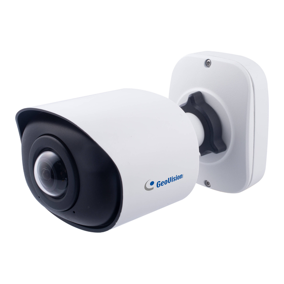
Fixed Bullet IP Camera 1.2.1 GV-PBL8800... -
Page 6: Quick Installation Steps
2. Quick Installation Steps Fixed Rugged IP Dome Camera Installation Loosen the setscrew and take the bracket off. Note: There are two setscrews on the camera that fasten the bracket. Loose either one or both setscrews until the bracket can be taken off. Only one of the setscrews needs to be screwed while fixing. - Page 7 Step 1: Buckle the lanyard on the camera body tightly to the reserved hook on the bracket. After connecting the cables to the respective connectors, twine the cables around tidily in the room on the bottom. Step 2: Rotate the camera to bracket and tighten the setscrew. Step 3: Loosen clamp screw and adjust shooting direction, tighten clamp screw.
-
Page 8: Fixed Bullet Ip Camera Installation
Fixed Bullet IP Camera Installation Step 1: Connect the cables to the corresponding interface on the rear cover of the Junction Box. Then fix the rear cover on the position where it is intended to be installed. The rear cover can be fixed in the following two ways: 1. -
Page 9: Waterproofing The Connector
3. Waterproofing the Connector Step 1: Get the network cable through the screw nut, rubber ring and the screw bolt. Step 2: Insert the rubber ring into the screw bolt. Step 3: Connect the screw nut to the screw bolt. Step 4: Place the O-Ring on the network port connector, tighten the screw bolt and the connector. -
Page 10: Accessing The Network Camera
4. Accessing the Network Camera Looking Up the Dynamic IP Address By default, when the camera is connected to LAN with DHCP server, it is automatically assigned with a dynamic IP address. Follow the steps below to look up its IP address. Note this function is only applicable on GV-IP Device Utility V8.9.7.0 or later. -
Page 11: Configuring The Ip Address
Configuring the IP Address If the camera is connected to a LAN without DHCP server, the default IP address will be 192.168.0.10. Follow the steps below to modify the IP address to avoid IP conflict with other GV-IP devices on the same LAN. 1. -
Page 12: The Web Interface
5. The Web Interface After logging in the camera’s Web interface, the user is allowed to view live videos as follows. Description Parameter Click to access the live view page. Live Video Click to access the playback page. Playback... - Page 13 Click to access the configuration page. Note: See Chapter 8 of GV-IP Panoramic Cameras User Manual for details. Settings Click to select system language. Display the user name and click to logout. Choose the stream (Primary/Secondary/Tertiary) to show on the current video window. Choose the options (Hide Detection Region/Region Entrance/ Region Exiting/Advanced Motion/Line Crossing/Loitering/ People Counting/Object...
- Page 14 Stop/Play live view. Stop/Play Click to capture the current image and save to the Snapshot configured path. Click to Start Recording video and save to the Start/Stop configured path. Click again to Stop Recording. Recording When enabled, you can zoom in in a specific area of Digital Zoom video image with your mouse wheel.
- Page 15 Brightness: Adjust the Brightness of the scene. Contrast: Adjust the color and light contrast. Saturation: Adjust the saturation of the image. Higher saturation makes colors appear “purer” while lower one appears more “washed-out”. Sharpness: Adjust the sharpness of image. Higher sharpness sharpens the pixel boundary and makes the image look “clearer”.
-
Page 16: Upgrading System Firmware
6. Upgrading System Firmware GeoVision periodically releases updated firmware on the company website. To load the new firmware into the camera, follow the instructions below. 1. At the top, select System > Maintenance > System Maintenance. This page appears. Click the button under System Upgrade to locate the firmware file saved at your local computer. -
Page 17: Restoring To Factory Default
7. Restoring to Factory Default If for any reason the camera is not responding correctly, you can restore the camera back to its factory default settings using the Web interface or the Default Button. 1. On the Web interface, click Settings. 2.
Need help?
Do you have a question about the GV-PBL8800 and is the answer not in the manual?
Questions and answers