Advertisement
Quick Links
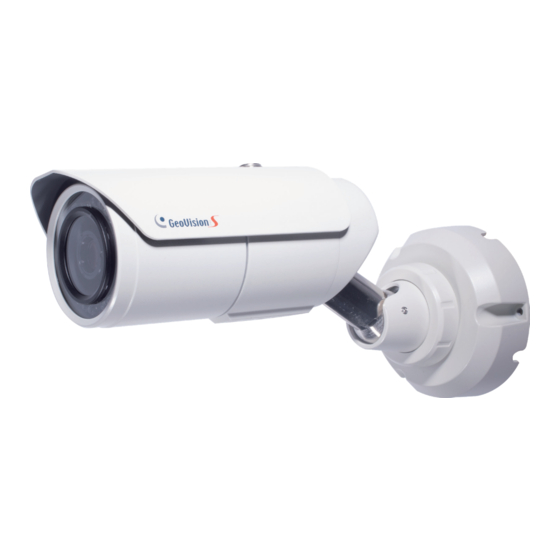
GV-LPR2811-DL Camera
Installation Guide
Thank you for purchasing GV-LPR2811-DL Camera. This guide is designed to inform users
of certain installation guidelines and tips before installing the camera. For advanced
information on how to use GV-LPR2811-DL, please refer to GV-LPR2811-DL Camera User's
Manual.
LPR2811-DL-IG-A
Advertisement

Summary of Contents for GeoVision GV-LPR2811-DL
- Page 1 GV-LPR2811-DL Camera Installation Guide Thank you for purchasing GV-LPR2811-DL Camera. This guide is designed to inform users of certain installation guidelines and tips before installing the camera. For advanced information on how to use GV-LPR2811-DL, please refer to GV-LPR2811-DL Camera User’s Manual.
- Page 2 GeoVision. Every effort has been made to ensure that the information in this manual is accurate. GeoVision, Inc. makes no expressed or implied warranty of any kind and assumes no responsibility for errors or omissions. No liability is assumed for incidental or consequential damages arising from the use of the information or products contained herein.
- Page 3 Contents 1. Installation and Recognition Parameters ..............2 2. Wire Definition ......................5 3. Common Problems ...................... 6...
- Page 4 Before installing GV-LPR Cameras, please read through this document carefully to ensure the captured images are suitable for license plate recognition. 1. Installation and Recognition Parameters View Angle ⚫ Vertical View Angle ≦ 30°: The vertical view angle of the camera shall be within 30 degrees to the ground.
- Page 5 ⚫ Parking Entrance/Exit: For installing at a parking entrance/exit, the camera shall be mounted at a recommended height of 1 ~ 3 meters (3.3 ~ 9.8 ft) with an optimal recognition distance of 4.5 ~ 22 meters (14.8 ~ 72.2 ft) while the speed of the target vehicle cannot be more than 30 km/h (18 mi/h).
- Page 6 ⚫ Centered-Top: For installing at the top of the center of a road, the camera shall be mounted at a recommended height of 5 ~ 6 meters (16.4 ~ 19.7 ft), with an optional recognition distance of 8 ~ 22 meters (26.2 ~ 72.2 ft), while the speed of the target vehicle cannot exceed 100 or 60 km/h (62 or 37 mi/h), respectively for single-laned and dual-laned roads.
- Page 7 2. Wire Definition The data cable provides connection for power, ground and network access. The wires are defined as below: Wire Definition RJ-45 Ethernet / PoE (IEEE 802.3af) 2-pin terminal block DC 12V Pink RCA Audio Input Green RCA Audio Output Blue DI 1 Green...
- Page 8 3. Common Problems ⚫ Low Image Contrast: Adjust the image contrast and/or improve lighting conditions of the recognition site. ⚫ Large Roll, Yaw and Pitch Angles: Adjust the angle and direction of the camera.
- Page 9 ⚫ Overexposed Images: Reduce the illumination or adjust the angle/direction of the camera. ⚫ Blurry Images: Adjust the focus or the shutter speed of the camera. ⚫ Hollow Characters: Reduce the illumination. ⚫ Plate Covered in Shadow: Avoid placing the camera where it is subjected to direct sunlight, reflections or shadows, which may limit recognition performance.


Need help?
Do you have a question about the GV-LPR2811-DL and is the answer not in the manual?
Questions and answers