ETC ArcSystem Pro D4 Series Installation Manual
Hide thumbs
Also See for ArcSystem Pro D4 Series:
- Installation manual (68 pages) ,
- Installation manual (29 pages)

Related Manuals for ETC ArcSystem Pro D4 Series


Summary of Contents for ETC ArcSystem Pro D4 Series
- Page 1 ArcSystem Pro D4 Series Drivers Installation Guide Part Number: 7490M2170 Rev: F Released: 2023-02...
- Page 2 To view a list of ETC trademarks and patents, go to etcconnect.com/ip. All other trademarks, both marked and not marked, are the property of their respective owners. ETC intends this document, whether printed or electronic, to be provided in its entirety.
-
Page 3: Table Of Contents
Table of Contents Introduction Document Conventions Help from ETC Technical Services Safety Label Symbols Chapter 1 System Overview ArcSystem Pro One-Cell and Pro One-Cell Small Luminaires Third-Party Fixtures D1 Series, D2 Series, and D4 Series Drivers TX1 Transmitter ArcMesh ArcMesh Specifications... - Page 4 DMX In and DMX Thru D4 Driver 150 Current Configuration Chapter 4 D4 Series Rack-Mount Driver Installation Electrical and Wiring Specification Prepare for Rack-Mount Installation Rack-Mounting Safety Terminate Wiring Power Input Wiring Output Wiring to Fixture Bridging Output Channels DMX In and DMX Thru Chapter 5 One-Cell Luminaire Installation Installing One-Cell Recessed Luminaires...
- Page 5 Output Channels Voltage Drop Wall-Mount Bridging Kits Rack-Mount Bridging Kits Output Channel Control Switches Example Bridge Configurations Bridging Procedure Appendix B Compliance Table of Contents...
- Page 6 D4 Series Drivers Installation Guide...
-
Page 7: Introduction
ArcSystem Pro One-Cell luminaires, D4 Series Drivers, and full system integration. For more information on ArcMesh or other ArcSystem Pro drivers and luminaires, see the manuals listed below. All ETC manuals are available for download free of charge at etcconnect.com. -
Page 8: Help From Etc Technical Services
Help from ETC Technical Services If you have questions that are not answered by this document, try the ETC support website at support.etcconnect.com or the main ETC website at etcconnect.com. If none of these resources are sufficient, contact ETC Technical Services directly at one of the offices identified below. -
Page 9: Safety
Safety ArcSystem products are intended for professional use only. Read the entire manual before using this equipment. IMPORTANT SAFEGUARDS When using electrical equipment, basic safety precautions should always be followed including the following: READ AND FOLLOW ALL SAFETY INSTRUCTIONS • Do not use outdoors. •... -
Page 10: System Overview
If your load is not in the compatibility database, follow the instructions at the link above to contact the ETC Applications Engineering department to arrange for compatibility testing. Third-party constant current fixtures or constant voltage fixtures can be connected directly to a D4 CC driver or D4 CV driver using the terminal outputs. -
Page 11: D1 Series, D2 Series, And D4 Series Drivers
D1 Series, D2 Series, and D4 Series Drivers D1 Driver D1 HO Driver D2 Driver Wall-Mount D4 Driver 150 (also available in 350 and 700 models) Rack-Mount D4 Driver 350 (also available in 700 model) Note: Antenna is not present on RDM models. ArcSystem Pro One-Cell luminaires require an external driver. -
Page 12: Tx1 Transmitter
All ArcSystem wireless luminaires require a TX1 Transmitter and commissioning tool to set DMX addresses for both wired DMX and wireless installations. Contact your ETC Service Technician for more information. Note: By default the TX1 DMX output is disabled. If you require DMX output from the TX1, you must use the ArcSystem comissioning tool software to add DMX fixtures. -
Page 13: Arcmesh Specifications
ArcMesh Specifications • Use up to 100 devices per TX1 transmitter. • Patch up to 64 ArcMesh channels to 512 DMX channels. • Use up to 16 TX1 transmitters per system. There are no system range limitations for transmitting data between luminaires because each luminaire has the ability to act as a repeater (see Re-Broadcast Mode below). - Page 14 Emergency drivers and luminaires require two branch circuit connections. These inputs have the following functions: 1. Normal branch circuit to sense failure of the normal supply. Connect to Sense Input connector. 2. Normal/Emergency branch circuit providing power to the luminaire in both conditions. Connect to Maintained Input connector.
-
Page 15: Before You Begin Installation
Before You Begin Installation Review the following sections before beginning your ArcSystem installation. ArcSystem products should only be installed by a qualified installer or electrician. Power Disconnect Device Before installation, make sure you have a readily accessible input power disconnect device installed ahead of your ArcSystem products. - Page 16 Voltage drop calculations vary by project and are based on the type, length, and gauge of wire used between the D4 Driver and load. Contact a qualified electrician or ETC technical services for further information. D4 Series Drivers Installation Guide...
-
Page 17: Preparing The Ceiling For Recessed Luminaires
Chapter 2 Preparing the Ceiling for Recessed Luminaires This section is specific to recessed (flush-mount) luminaires. For yoke-mounted luminaires, see Installing One-Cell Yoke-Mounted Luminaires on page 28 The luminaire retaining clips accommodate Luminaire Minimum Hole Diameter 3–24 mm (1/8–15/16 in) ceiling thickness. Pro One-Cell 16.5 cm (6-1/2 in) Cut a hole in the ceiling or ceiling tile to... -
Page 18: Extension Cables
Extension Cables Extension cables can be used Part Number Description between an ArcSystem Pro D1 ARCDAHBC1 1 m (3 ft 3 in) extension cable Series, D2 Series, or D4 CC driver and a compatible ArcSystem Pro ARCDAHBC2 2 m (6 ft 7 in) extension cable One-Cell, One-Cell Small, or One- ARCDAHBC3 3 m (9 ft 10 in) extension cable Cell Micro luminaire. -
Page 19: D4 Series Wall-Mount Driver Installation
Install the D4 Driver on a power distribution system with reliably identified earthed neutral and install a maximum appropriately-sized circuit breaker on the line conductor. ETC recommends installing all wiring to and from wall-mount drivers in grounded metal conduit. The wall-mount D4 150 CC driver accepts 100–240 VAC, 50/60 Hz or 277 VAC, 50/60 Hz (models ending in "-277"). -
Page 20: Wire And Terminal Specifications
Wire and Terminal Specifications Terminal / Connector Wire Range / Specification Strip Length Torque Rating Standard and emergency models maintained 0.5 Nm 7 mm input (line/neutral): (1/4 in) D4 150 CV standard (4 in-lb) 0.5–10 mm (22–6 AWG) and emergency driver Standard and emergency models maintained Power Input 10 mm 4.0 Nm... -
Page 21: Prepare For Wall-Mount Installation
Prepare for Wall-Mount Installation Note: Mounting hardware and installation location must support the weight of the driver, conduit hardware, and all cable required for installation. Wall-Mounting Supplies The following supplies are required, but not provided, for D4 Driver installation: • flexible conduit and conduit fittings •... -
Page 22: Terminate Wiring
Terminate Wiring Wiring of the driver consists of wiring power and data (DMX) to the driver for your luminaire and then running power out to the luminaire from the driver. If you are installing emergency system drivers, Emergency System One-Cell Installation on page 29 Wall-Mount Driver Wiring Overview LED4 LED3... - Page 23 D4 Driver 350 D4 Driver 700 Power input Output channels Antenna* DMX input and thru (RJ45) DMX input and thru (eight-pin terminal blocks)† *The antenna is not present on RDM models. †Eight-pin terminal blocks are not present on D4 Driver 150. D4 Series Wall-Mount Driver Installation...
-
Page 24: Power Input Wiring
Power Input Wiring This section provides power input wiring termination for standard wall-mount D4 Driver models. See Emergency System One-Cell Installation on page 29 D4 Driver 150 Factory Wire Colors Model Color Type North America green/yellow ground/earth and Europe North America black line/hot North America... - Page 25 Wall-Mount D4 Driver 350 and 700 Push-In Terminal Blocks D4 Driver 350 and 700 wall-mount drivers have push-in terminal blocks. No tools are required to insert wires into the terminal block. Install Wire Remove Wire A terminal B tool slot (square) •...
-
Page 26: Output Wiring
Connect the Input Power 1. Make sure power is off at the main circuit breaker. 2. See Wire and Terminal Specifications on page 14 for specification of wire size and strip length. Prepare the wires accordingly. 3. See Push-In Terminal Blocks on the previous page for general instructions on using the push-in terminal blocks. -
Page 27: Dmx In And Dmx Thru
D4 drivers are not self-terminating. You must terminate the last driver in line with a DMX terminator plug in the RJ45 Thru receptacle. To purchase an RJ45 terminator, please contact your ETC customer service representative and request part number N4086. -
Page 28: D4 Driver 150 Current Configuration
Switches 2 through 5 are factory set to allow each output to be controlled by an individual DMX address. ETC recommends leaving the DMX channel switches (positions 2 through 5) at their factory settings and using the ArcSystem Configuration Software or RDM settings to control the behavior of each output. -
Page 29: D4 Series Rack-Mount Driver Installation
Chapter 4 D4 Series Rack-Mount Driver Installation This section provides information on how to install rack-mount D4 series constant voltage drivers. Up to 32 drivers can be installed on one hard-wired line of DMX. Electrical and Wiring Specification WARNING: Circuits that are installed without an accessible power disconnect device cannot be serviced or operated safely. -
Page 30: Rack-Mounting Safety
(104°F). • Mechanical Loading: Only mount the D4 Driver in an equipment rack using the included ETC rack-mount hardware. Mount in a horizontal orientation to ensure even mechanical loading in the rack, avoiding hazardous or dangerous loading conditions. • Circuit Overloading: When installing the D4 Driver in an equipment rack, consider the connection of the equipment to the rack or power source to avoid overloading the rack circuit or supply wiring. -
Page 31: Power Input Wiring
Power Input Wiring 1. Ensure power to the rack is off. 2. Connect the AC input to the AC power source using the provided power input cord. Output Wiring to Fixture D4 Series rack-mount drivers have two-pin terminal outputs that can be used to provide power and data to other fixtures. -
Page 32: Dmx In And Dmx Thru
D4 drivers are not self-terminating. You must terminate the last driver in line with a DMX terminator plug in the RJ45 Thru receptacle. To purchase an RJ45 terminator, please contact your ETC customer service representative and request part number N4086. -
Page 33: One-Cell Luminaire Installation
Chapter 5 One-Cell Luminaire Installation This chapter provides information on how to install ArcSystem Pro One-Cell luminaires in a standard ArcSystem installation. Installing One-Cell Recessed Luminaires The installation procedure is similar for all recessed one-cell luminaires (fixed and adjustable). Installing One-Cell Yoke-Mounted For Pro One-Cell yoke-mounted luminaires, continue on to Luminaires on the next page WARNING:... -
Page 34: Installing One-Cell Yoke-Mounted Luminaires
Installing One-Cell Yoke-Mounted Luminaires 1. Attach a C-clamp or other mounting hardware (not provided) to the yoke of the luminaire. 2. Attach the luminaire to a pipe or other approved mounting device. D4 Series Drivers Installation Guide... -
Page 35: Emergency System One-Cell Installation
Chapter 6 Emergency System One-Cell Installation With the exception of power input terminations, ArcSystem emergency system installation requirements are the same as those of the standard ArcSystem. Complete the appropriate steps for your installation, referencing the following sections for any additional installation details before wiring the power: •... -
Page 36: Wall-Mount Emergency Drivers
Wall-Mount Emergency Drivers LED4 LED3 Switch Output type blocks varies by model LED2 LED1 SENSE SENSE D4 Emergency Driver Constant Current with Molex connectors Constant Current with terminal outputs Constant Voltage with terminal outputs D4 Series Drivers Installation Guide... - Page 37 D4 Emergency Driver 350 D4 Emergency Driver 700 Maintain (emergency) power input Sense (normal sense) power input Output channels Antenna* DMX input and thru (RJ45) DMX input and thru (eight-pin terminal blocks)† *The antenna is not present on RDM models. †Eight-pin terminal blocks are not present on D4 Driver 150.
-
Page 38: Wall-Mount Emergency Driver Installation
Wall-Mount Emergency Driver Installation CAUTION: RISK OF SHOCK AND FIRE - This unit has more than one power supply connection point. To reduce the risk of electric shock disconnect both the branch circuit-breakers or fuses and emergency power supplies before servicing. ATTENTION : RISQUE D'INCENDIE ET DE CHOC - Cet appareil posséde plusieurs points de connexion d'alimentation. - Page 39 Terminate Normal Sense Input WARNING: Circuits that are installed without an accessible power disconnect device cannot be serviced or operated safely. AVERTISSEMENT : Il est imprudent d'utiliser ou de réparer les circuits installés sans qu'un dispositif de déconnexion de l'alimentation ne soit accessible.
- Page 40 Wall-Mount D4 Emergency Driver 350 or 700 Wall-Mount D4 Emergency Driver 350 and 700 have push-in terminal blocks on the "Sense" Push- and "Maintain" inputs. No tools are required to insert wires into the terminal block. See In Terminal Blocks on page 19 for an illustration of the push-in terminal blocks.
- Page 41 Terminate Maintained (Emergency) Input D4 Emergency Driver 150 Note: The maintained input in a D4 Series driver is the input labeled "L N ". The D4 sense input is labeled " N L Sense". Connect maintained input to a normal/emergency branch circuit with upstream UL 1008 automatic transfer switch.
-
Page 42: Rack-Mount Emergency Drivers
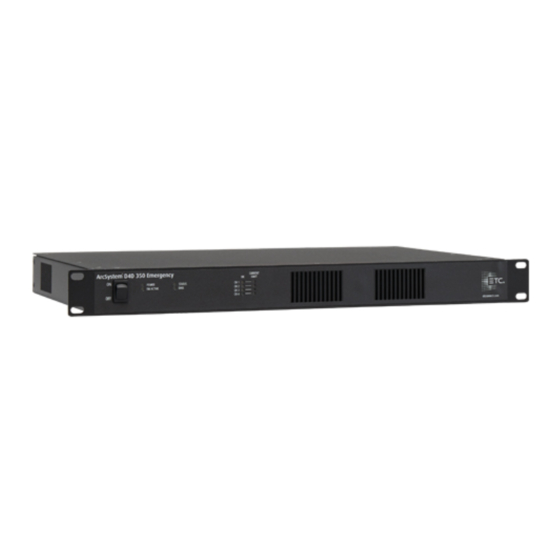
Rack-Mount Emergency Drivers Rack-Mount D4 Emergency Driver 350 Rack-Mount D4 Emergency Driver 700 A Output channel "CH 1" E "DMX In" Output channel "CH 2" F "DMX Thru" C Output channel "CH 3" G Maintained power input cord (bare end) D Output channel "CH 4" H Normal/Sense power input cord (bare end) D4 Series Drivers Installation Guide... - Page 43 Rack-Mount Emergency Driver Installation WARNING: RISK OF DEATH BY ELECTRIC SHOCK! Before you begin pulling and terminating wire to the ArcSystem Driver enclosure or TX1 Transmitter, make sure the main circuit breaker cabinet or other readily accessible input power disconnect device for the normal power input (and emergency power input when used) is locked out and tagged out.
-
Page 44: Final Installation And Operation
All ArcSystem luminaires are factory set to provide 100% output level. This allows an electrical contractor to check that all products are properly installed and wired. During system commissioning, the certified ETC technician will remove this setting and configure DMX addresses for normal use. During normal use after commissioning is complete, ArcSystem luminaires will light if the DMX Control level is greater than 0. -
Page 45: Commissioning A Wireless Arcsystem
Initial programming of a wireless ArcSystem requires a USB commissioning tool (ARCMCT), and existing hardware such as a laptop or desk top computer that is connected to ArcSystem. This programming will be carried out by an ETC certified technician at the time of system commissioning and training. -
Page 46: Rdm Values
ArcSystem wireless luminaires ARC-TX1 DMX512 DMX512 DMX512 from lighting console ArcSystem wired DMX luminaires Third party DMX devices Note: By default the TX1 DMX output is disabled. If you require DMX output from the TX1, you must use the ArcSystem comissioning tool software to add DMX fixtures. RDM Values Manufacturer ID: 0x6574 (Electronic Theatre Controls) Model IDs... - Page 47 Parameter RDM PID Value Notes Default is 001. The upper limit for the D4 DMX Start Address 0x00F0 Range = 001 to 512 Series drivers is 508. Default is 2. This parameter sets the number of DMX channels available on a D4 Series driver. DMX Personality 0x00E0 1 or 2...
-
Page 48: Maintenance
être remplacées seulement par un technicien qualifié. Contactez le service client ETC pour obtenir de l’assistance. WARNING: Disconnect the fixture from power and DMX and allow it to cool before performing any cleaning and maintenance. -
Page 49: Emergency Operation And Test
A can of compressed air or oil-free air from an air compressor set at a low setting can be used to blow through the vent holes and remove dust or other debris. Dust buildup can cause overheating and premature shutdown. All components can be cleaned using compressed, oil-free air as described above or a clean micro-fiber cloth. -
Page 50: Troubleshooting
- all output channels are on at 100%. models only) D4 Driver 700 and D4 Emergency Driver 700 only PSU 1 Fault On: power supply 1 has a fault. Contact ETC Technical Services for assistance. D4 Driver 700 and D4 Emergency Driver 700 only PSU 2 Fault On: power supply 2 has a fault. -
Page 51: Overload Protection
Overload Protection D4 series drivers have two types of maximum output limit: warning and trip. Contact ETC technical services for assistance with warning and fault conditions. Warning On D4 Driver 350 and 700 models only, the "Channel OK" LED will remain solid on and the Channel Limit LED will light if the current drawn on any channel exceeds the warning limits. -
Page 52: Appendix A Bridge D4 Series Constant Voltage Driver
Appendix A Bridge D4 Series Constant Voltage Driver Output Channels It is acceptable to bridge multiple output channels together on an ArcSystem D4 Series Constant Voltage Driver, ganging the maximum output allowed into a single combined output channel. See below for examples of the configurations made possible by bridging output channels. - Page 53 AVERTISSEMENT : Vous devez utiliser un kit de câblage agréé et fourni par ETC. Ne pontez pas les circuits de sortie avec des fils ou du matériel non agréés. Note: Power wiring should only be installed and terminated by a qualified electrician and should follow standard wiring installation practices.
-
Page 54: Voltage Drop
Voltage drop calculations vary by project and are based on the type, length, and gauge of wire used between the D4 Driver and load. Contact a qualified electrician or ETC technical services for further information. Wall-Mount Bridging Kits 1. -
Page 55: Output Channel Control Switches
Output Channel Control Switches Each output channel on the D4 Driver is controlled by a switch block (S1–S4, shown below). Switch positions 2–5 are factory set to allow individual control of each output. In order to bridge channels together, you must adjust the positions of switches 2–5. LED 4 LED 3 Switch... - Page 56 Switch Blocks Each of the four switch blocks controls one output channel. • Switch block S1 controls the output channel labeled "LED 1" on D4 Driver 150 or "CH 4" on D4 Driver 350 and 700. • Switch block S2 controls the output channel labeled "LED 2" on D4 Driver 150 or "CH 3" on D4 Driver 350 and 700.
- Page 57 Setting Switches 2 Through 5 for Bridged Output Channels Note: Each output channel that you want to bridge must have the same setting for switch positions 2–5 as the other output channels in the bridge. Output channels that are electrically connected (bridged) with different switch settings may have reduced capacity.
-
Page 58: Example Bridge Configurations
Example Bridge Configurations All Four Output Channels Bridged Bridging four output channels can be done as shown below for maximum load capacity on one circuit and control on output channel 1. The bridged circuit can be assigned to any output channel as long as all four switch blocks (S1–S4) are set the same. The illustration and table below show all four output channels bridged together to form bridged output channel 1. - Page 59 Output Channels Bridged in Pairs Bridging pairs of output channels can be done as shown below for control on output channel 1 and output channel 2, or on any pair of output channels as long as the output channels that are electrically connected (bridged) have the same switch block settings. The illustrations and table below show output channel 1 and output channel 2 bridged to form bridged output channel 1 and output channel 3 and output channel 4 bridged to form bridged output channel 3.
- Page 60 Three Output Channels Bridged Bridging three output channels can be done as shown below for control on output channel 1, or on any channel as long as the three output channels that are electrically connected (bridged) have the same switch block settings. The fourth output channel can be assigned to any of the three remaining channels.
-
Page 61: Bridging Procedure
Bridging Procedure The steps below describe how to bridge output channels on wall-mount and rack-mount D4 Driver models. Wall-mount D4 Driver models have four two-position screw-terminal connections located inside the enclosure. Rack-mount D4 Driver 350 and 700 models have four two-position screw-terminal plugs installed in the back of the enclosure. Outputs are labeled "LED 1", "LED 2", "LED 3"... -
Page 62: Appendix B Compliance
32 device loads per daisy chain. This product is not self-terminating. You must terminate the last driver on the daisy chain with a 120 Ω resistor. To purchase an RJ45 terminator, please contact your ETC customer service representative and request part number N4086. For eight-pin DMX termination, you must terminate the last driver in line with a 120 Ω... - Page 63 Compliance...
- Page 64 | Support support.etcconnect.com | Contact etcconnect.com/contactETC © 2023 Electronic Theatre Controls, Inc. | Trademark and patent info: etcconnect.com/ip Product information and specifications subject to change. ETC intends this document to be provided in its entirety. 7490M2170 Rev F Released 2023-02...
Need help?
Do you have a question about the ArcSystem Pro D4 Series and is the answer not in the manual?
Questions and answers