Table of Contents
Advertisement
Quick Links
Advertisement
Table of Contents

Subscribe to Our Youtube Channel
Related Manuals for Kontron KBox B-101


Summary of Contents for Kontron KBox B-101
- Page 1 » User’s Guide « KBox B-101 User’s Guide (Version 1.00) 1056-8384 www.kontron.com...
- Page 2 This page is intentionally left blank. www.kontron.com...
-
Page 3: Table Of Contents
1. Table of Contents KBox B-101 – User’s Guide (Version 1.00) 1. Table of Contents 1. Table of Contents ............................. 1 1.1. Table of Figures............................2 2. Introduction ............................4 2.1. Symbols used in this Manual........................5 ... -
Page 4: Table Of Figures
Fig. 17: Expansion Slots of the KBox B-101 ......................21 Fig. 18: Lithium battery..........................22 Fig. 19: Desktop version of the KBox B-101, with rubber feet attached ..............24 Fig. 20: KBox B-101 with brackets for wall mounting installed ................25 ... - Page 5 1. Table of Contents KBox B-101 – User’s Guide (Version 1.00) Fig. 24: Dimensions in the side view and top view (desktop version)..............31 Fig. 25: Dimensions in the front view (wall mounting) ..................32 Fig. 26: Dimensions in the side view (wall mounting) ..................32 ...
-
Page 6: Introduction
Kontron does not accept any liability for any printing errors or other inaccuracies in the manual unless it can be proven that Kontron is aware of such errors or inaccuracies or that Kontron is unaware of these as a result of gross negligence and Kontron has failed to eliminate these errors or inaccuracies for this reason. -
Page 7: Symbols Used In This Manual
2. Introduction KBox B-101 – User’s Guide (Version 1.00) 2.1. Symbols used in this Manual Symbol Meaning This symbol indicates the danger of injury to the user or the risk of damage to the product if the corresponding warning notices are not observed. -
Page 8: Important Instructions
In the event of damage to the device caused by failure to observe the included document “General Safety Instructions for IT Equipment”, the hints in this manual or eventually the warning signs label on the device, Kontron shall not be required to honor the warranty even during the warranty period and shall be exempted from the statutory accident liability obligation.. -
Page 9: General Safety Instructions For It Equipment
If the following general safety instructions are not observed, it could lead to injuries to the operator and/or damage of the product; in cases of nonobservance of the instructions Kontron is exempt from accident liability, this also applies during the warranty period. -
Page 10: Electrostatic Discharge (Esd)
4. General Safety Instructions for IT Equipment KBox B-101 – User’s Guide (Version 1.00) Additional safety instructions for DC power supply circuits To guarantee safe operation of devices with DC power supply voltages larger than 60 volts DC or a power consumption larger than 240 VA, please observe that: •... -
Page 11: Instructions For The Lithium Battery
4. General Safety Instructions for IT Equipment KBox B-101 – User’s Guide (Version 1.00) 4.2. Instructions for the Lithium Battery The installed motherboard is equipped with a Lithium battery. When replacing the lithium battery, please follow the corresponding instructions in the subsection 8.1.2 “Replacing the Lithium Battery”. -
Page 12: Electromagnetic Compatibility (Class A Device)
5. Electromagnetic Compatibility (Class A Device) KBox B-101 – User’s Guide (Version 1.00) 5. Electromagnetic Compatibility (Class A Device) 5.1. Electromagnetic Compatibility (EU) This product is intended only for use in industrial areas. The most recent version of the EMC guidelines (EMC Directive 2004/108/EC) and/or the German EMC laws apply. -
Page 13: Scope Of Delivery
Brackets for wall mounting Brackets for table mounting 6.1. Type Label and Product Identification The type label (product name, serial number) of your KBox B-101 system is located at the left side of the device (refer to Fig. 15). Fig. 1: Front view Fig. -
Page 14: Product Description
(also if wall-mounted). When switching on the KBox B-101, make sure that the air openings on the front side (Fig. 9, pos. 4) and the rear side (Fig. 12, pos. 3) of the chassis are not obstructed (covered) by any objects. -
Page 15: Front Side
The 3-pin connector (Fig. 9, pos. 1) provides the power connection to a mains socket via a power cord. Please observe section 10.1 „AC Power Connection“. 7.1.2. Controls and Indicators Power button Power LED HDD LED Fig. 10: KBox B-101 – Controls and Indicators www.kontron.com... - Page 16 Power LED and HDD Activity LED 7.1.2.2. The power LED (Fig. 10, pos. 2) and the HDD LED (Fig. 10, pos. 3) are located on the front side of the KBox B-101 and indicate the system status. Power LED This LED (Fig.
-
Page 17: Interfaces On The Front Side
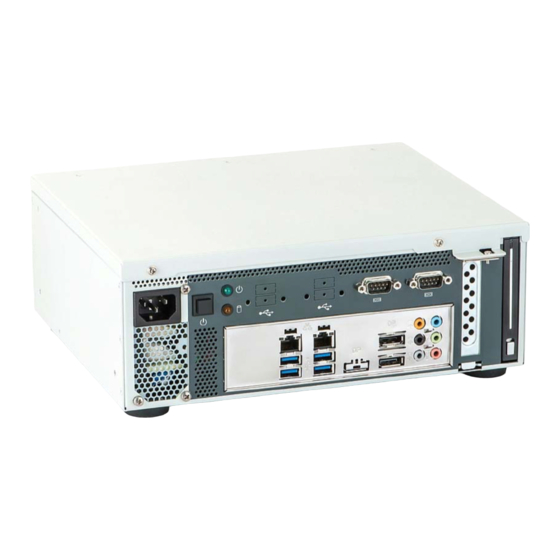
7. Product Description KBox B-101 – User’s Guide (Version 1.00) 7.1.3. Interfaces on the Front Side Fig. 11: External interfaces of the integrated motherboard 4x USB 2.0 port (USB4 - USB7) 2x USB 3.0 port (USB0, USB1) 2x serial port (COM1, COM2) 2x DisplayPort Connector (DP0, DP1) 2x USB 2.0 port (USB2, USB3) - Page 18 7. Product Description KBox B-101 – User’s Guide (Version 1.00) Display Port Connector 7.1.3.4. Two external (digital) displays can be connected to the DisplayPort connectors (DP0, DP1) (Fig. 11, pos. 6). Appropriate Monitors can be connected directly to the DisplayPort connectors using DisplayPort cables.
-
Page 19: Rear Side
7. Product Description KBox B-101 – User’s Guide (Version 1.00) 7.2. Rear Side Fig. 12: Rear side of the KBox B-101 1 Rear side of the KBox B-101 3 Air exhaust openings of the internal fan 2 Rubber feet (desktop version) -
Page 20: Right/Left And Top Side
7. Product Description KBox B-101 – User’s Guide (Version 1.00) 7.3. Right/Left and Top Side At the right and left side of the chassis, the threaded holes for attaching the optional mounting brackets are located. In addition, the type label is attached to the left side of the chassis. -
Page 21: Bottom Side
7. Product Description KBox B-101 – User’s Guide (Version 1.00) 7.4. Bottom Side Fig. 16: Bottom side (shown as desktop version) 1 Front side with external interfaces of the 2 Rubber feet (desktop version) installed motherboard If you intend to convert your device from the desktop version to a wall/table mount version, see also chapter 9 ”Setting up the KBox B-101”. -
Page 22: Handling Internal Components
8.1.1. Opening and Closing the KBox B-101 In order to install or to remove optional hardware or to change the DIP switch settings, the KBox B-101 needs to be opened. For opening and closing the KBox B-101, please perform the following steps: Before opening the KBox B-101, the system must be switched off and disconnected from the main power supply. -
Page 23: Installing/Removing Expansion Cards
In order to install/remove an expansion card, perform the following steps: 1. Open the KBox B-101, as described in subsection 8.1.1”Opening and Closing the KBox B-101” (steps 1 to 4). 2. After removing the cover, the PCIe slot, the Mini PCI Express slot and the mSATA slot are easily accessible (see Fig. -
Page 24: Replacing The Lithium Battery
3. Place a new lithium battery into the battery holder. 4. Pay attention to the polarity of the battery. 5. The lithium battery must be replaced with an identical battery or a battery type recommended by Kontron (Lithium battery 3.0 V for RTC, type: CR2032). -
Page 25: Setting Up The Kbox B-101
When mounted into a cabinet: the cabinet must have adequate space for the KBox B-101 platform, and corresponding spaces for air circulation and cable connections (see also section 12.2 “Mechanical Specifications”). -
Page 26: Kbox B-101 - Desktop Version
When setting up the device, make sure that the ventilation openings on the front and rear side of the chassis are not obstructed (covered) by any objects (refer to subsection 12.2.1 “KBox B-101 Desktop Dimensions”). Fig. 19: Desktop version of the KBox B-101, with rubber feet attached... -
Page 27: Wall/Table Mounting Using The Brackets
9.2. Wall/Table Mounting using the Brackets In order to mount the KBox B-101 to a wall, on a table or into a cabinet, you may order the corresponding mounting brackets. You can adapt your desktop KBox B-101 to a wall or table mount system by attaching the appropriate mounting brackets to the corresponding sides of the KBox B-101. -
Page 28: Brackets For Table Mounting
Table mounting (by using the corresponding brackets) is only possible without the rubber feet attached. Rubber feet that are already attached to the chassis of the KBox B-101 (e.g. when adapting a desktop version) must be removed before table mounting. -
Page 29: Starting Up
The AC input connector (Fig. 9, pos. 1) is located on the front side of the KBox B-101. The KBox B-101 can be connected to an AC supply circuit using an AC power cord (see Fig. 22). Even when the system is turned off via the power button (Fig. 10, pos. 1) there is still a standby-voltage of 5 VSb on the SBC. -
Page 30: Operating System And Hardware Component Drivers
Your system can be supplied optionally with a pre-installed operating system. If you have ordered your KBox B-101 with a pre-installed operating system, all drivers are installed in accordance with the system configuration ordered (optional hardware components). Your system is fully operational when you switch it on for the first time. -
Page 31: Maintenance And Prevention
KBox B-101 – User’s Guide (Version 1.00) 11. Maintenance and Prevention Equipment from Kontron requires only minimum servicing and maintenance for problem-free operation. For light soiling, clean the KBox B-101 with a dry cloth. Carefully remove dust from the surface of the cooling fins of the chassis using a clean, soft brush. -
Page 32: Technical Data
12. Technical Data KBox B-101 – User’s Guide (Version 1.00) 12. Technical Data KBox B-101 Motherboard Kontron KTH81Mini-ITX motherboard ® ® Supported Processors Intel 4th Gen. Core™ i7/i5/i3 and Pentium processors max.16 GB (2 x 8 GB) DDR3/DDR3L ® Chipset... -
Page 33: Electrical Specifications
KBox B-101 – User’s Guide (Version 1.00) 12.1. Electrical Specifications The corresponding electrical specifications for your KBox B-101 can be found on the type label of the system. The type label is located on the left side of the unit (refer to Fig. 15). -
Page 34: Dimensions For Wall Mounting
12. Technical Data KBox B-101 – User’s Guide (Version 1.00) 12.2.2. Dimensions for Wall Mounting For sufficient air circulation, make sure that the ventilation openings of the chassis are not obstructed (covered) by any objects. The wall mounting brackets provide enough space between the wall and the chassis (for the fan on the rear side of the chassis) (see Fig. -
Page 35: Dimensions For Table Mounting
12. Technical Data KBox B-101 – User’s Guide (Version 1.00) 12.2.3. Dimensions for Table Mounting For sufficient air circulation, make sure that the ventilation openings of the chassis are not obstructed (covered) by any objects. Fig. 27: Dimensions in the front view (table mounting) Fig. -
Page 36: Environmental Specifications
12. Technical Data KBox B-101 – User’s Guide (Version 1.00) 12.3. Environmental Specifications Operating Temperature 0 … +45 °C (32 … 113 °F) Storage/Transit Temperature -25 … +70 °C (-40 … +185 °F) Rel. Humidity (Operating) 95% @ 40 °C (non-condensing) -
Page 37: Ce Directives And Standards
12. Technical Data KBox B-101 – User’s Guide (Version 1.00) 12.4. CE Directives and Standards CE Directive Electrical Safety General Product Safety Directive (GPSD) 2001/95/EC Low Voltage Directive (LVD) 2006/95/EC Electromagnetic EMC Directive 2004/108/EC Compatibility (EMC) CE Marking CE Directive 93/68/EEC... -
Page 38: Standard Interfaces - Pin Assignments
13. Standard Interfaces – Pin Assignments KBox B-101 – User’s Guide (Version 1.00) 13. Standard Interfaces – Pin Assignments Low-active signals are indicated by a minus sign. 13.1.1. Serial Interfaces COM 1 and COM 2 (RS232) Signal Name 9-pin D-SUB Connector... -
Page 39: Usb 2.0 Port
13. Standard Interfaces – Pin Assignments KBox B-101 – User’s Guide (Version 1.00) 13.1.3. USB 2.0 Port Signal Name 4-pin USB Connector Typ A Version 2.0 Data- Data+ 13.1.4. USB3.0 Port Signal Name 9-pin USB Connector Type A Version 3.0/2.0 USB 2.0 Contacts... -
Page 40: Technical Support
Be ready to explain the nature of your problem to the service technician. If you have questions about Kontron or our products and services, you can reach us by the above-mentioned telephone www.kontron.com number and on e-mail address or at: 14.1.
Need help?
Do you have a question about the KBox B-101 and is the answer not in the manual?
Questions and answers