
Related Manuals for Kontron KBox B-201-CFL


Summary of Contents for Kontron KBox B-201-CFL
- Page 1 USER GUIDE KBox B-201-CFL Doc. User Guide, Rev. 1.0 Doc. ID: 1065-0689 www.kontron.com // 1...
- Page 2 KBox B-201-CFL - User Guide, Rev. 1.0 This page has been intentionally left blank www.kontron.com // 2...
- Page 3 In cases of doubt, please contact Kontron. This user guide is protected by copyright. All rights are reserved by Kontron. No part of this document may be reproduced, transmitted, transcribed, stored in a retrieval system, or translated into any language or computer language, in any form or by any means (electronic, mechanical, photocopying, recording, or otherwise), without the express written permission of Kontron.
- Page 4 PHYSICAL OR ENVIRONMENTAL DAMAGE (COLLECTIVELY "HIGH RISK APPLICATIONS"). You understand and agree that your use of Kontron products as a component in High Risk Applications is entirely at your own risk. To minimize the risks associated with your systems and applications, you must provide adequate design and operating safeguards.
- Page 5 If you have any difficulties using this user guide, discover an error, or just want to provide some feedback, contact Kontron support. Detail any errors you find. We will correct the errors or problems as soon as possible and post the revised user guide on our website.
-
Page 6: Symbols
KBox B-201-CFL - User Guide, Rev. 1.0 Symbols The following symbols may be used in this user guide DANGER indicates a hazardous situation which, if not avoided, will result in death or serious injury. WARNING indicates a hazardous situation which, if not avoided, could result in death or serious injury. -
Page 7: For Your Safety
Therefore, in the interest of your own safety and of the correct operation of your new Kontron product, you are requested to conform with the following guidelines. -
Page 8: Lithium Battery Precautions
General Instructions on Usage In order to maintain Kontron’s product warranty, this product must not be altered or modified in any way. Changes or modifications to the product, that are not explicitly approved by Kontron and described in this user guide or received from Kontron Support as a special handling instruction, will void your warranty. -
Page 9: Table Of Contents
KBox B-201-CFL - User Guide, Rev. 1.0 Table of Contents Symbols ..........................................6 For Your Safety ........................................7 High Voltage Safety Instructions .................................. 7 Special Handling and Unpacking Instruction ............................7 Lithium Battery Precautions ..................................8 General Instructions on Usage ..................................8 Quality and Environmental Management .............................. - Page 10 10.1. System Block Diagrams ..................................48 10.2. Technical Specification ..................................50 10.3. Mechanical Specification ..................................52 10.3.1. Dimension Diagrams – KBox B-201-CFL ............................. 52 10.3.2. Dimension Diagrams- Wall Mount Brackets ..........................54 10.4. Environmental Specification ................................54 10.5. Directives and Standards ..................................55 10.6.
-
Page 11: List Of Tables
Table 9: Power Supply Specification ................................51 Table 10: Mechanical Specifications ................................. 52 Table 11: Environmental Specification ..............................54 Table 12: Directives and Standards Compliance for KBox B-201-CFL ................... 55 Table 13: Power Supply Unit (PSU) Specification ..........................56 Table 14. Power Consumption ..................................56 Table 15: DC power Jack Pin Assignment .............................. - Page 12 Figure 29: Inserting the Band ..................................43 Figure 30: Positioning the PSU ..................................43 Figure 31: KBox B-201-CFL and PSU Mounting Position ........................43 Figure 32: Non VESA Stand Monitor Assembly ............................44 Figure 33: Installed VESA 100 Mount Assembly – non VESA Stand Monitor ................44 Figure 34: VESA Monitor Stand Assembly...............................
-
Page 13: 1/ General Safety Instructions For It Equipment
Kontron is exempt from accident liability, this also applies during the warranty period. The product has been built and tested according to the basic safety requirements for low voltage (LVD) applications and has left the manufacturer in safety-related, flawless condition. - Page 14 KBox B-201-CFL - User Guide, Rev. 1.0 Additional safety instructions for DC power supply circuits To guarantee safe operation of product s with DC power supply voltages larger than 60 volts DC or a power consumption larger than 120 VA, please observe that: ...
- Page 15 KBox B-201-CFL - User Guide, Rev. 1.0 1.2. Instructions for the Lithium Battery The KBox B-201-CFL’s mainboard is equipped with a lithium battery. When replacing the battery please observe the instructions described in Chapter 14.3.1: Replacing Lithium Battery. Danger of explosion when replacing with wrong type of battery. Replace only with the same or equivalent type recommended by the manufacturer.
-
Page 16: 2/ Introduction
New users are recommended to study the installation instructions within this user guide before switching on the power. The KBox B-201-CFL is part of Kontron’s Box PC family designed for high performance needs in a small form factor. Based on the Intel® 8 generation platforms with mini ITX mainboard, the KBox B-201-CFL features high processing capability and long-term availability. -
Page 17: 3/ Scope Of Delivery
3.1. Packaging The KBox B-201-CFL is packaged together with all standard parts listed in Table 1: Scope of Delivery, in a product specific cardboard package designed to provide adequate protection and absorb shock. 3.2. Type Label and Product Identification The type label on the KBox B-201-CFL contains important product information and indicates the product variants;... -
Page 18: 4/ Product Overview
KBox B-201-CFL - User Guide, Rev. 1.0 4/ Product Overview Before working with the KBox B-201-CFL, Kontron recommends that users take a few minutes to learn about the product’s various parts. The following chapter provides information regarding KBox B-201-CFL features. -
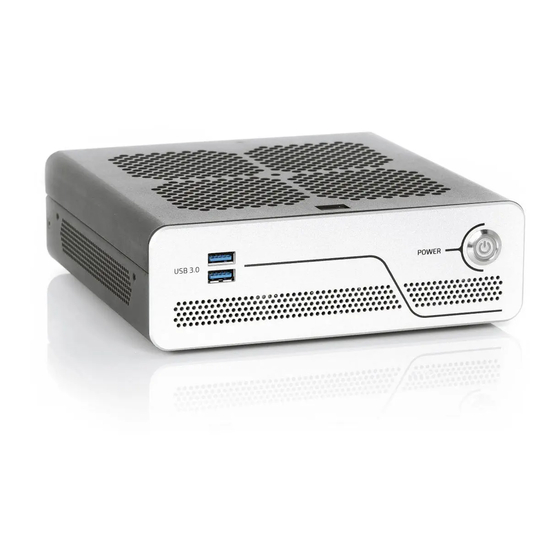
Page 19: Front Side
4.1.1. Front Connectors and Buttons 4.1.1.1. Power-On Button The power-on button powers on/off the KBox B-201-CFL. The power-on button includes an integrated power LED that lights up blue to indicate the powered on state. By pressing the power-on button for longer than four seconds initiates a forced system shutdown, before turning off the power to the system. -
Page 20: Rear Side
The rear panel contains the main I/O interfaces, power-in connector (DC-IN), ventilation holes for air-output and two top cover fastening screws. The KBox B-201-CFL (Smart and Value) variants support different rear panel I/O interfaces, as shown in Figure 5 and Figure 6. -
Page 21: Rear Panel Connectors
The USB 2.0 ports enable the connection of USB 2.0 compatible devices to the system. The number of USB 2.0 ports depends on the KBox B-201-CFL variant (Smart or Value) see Figure 5, pos. 3 and Figure 6, pos. 3 and 8. - Page 22 DP to HDMI (passive + active), DP to DVI (passive + active) and DP to VGA (active only) adapters. The number of DP connectors depends on the KBox B-201-CFL variant (Smart or Value) see Figure 5, pos.
- Page 23 The USB 3.1 Gen 1 ports are backwards compatible enabling the connection of both USB 3.0 or USB 2.0 compatible devices. The number of USB 3.1 Gen 1 ports depends on the KBox B-201-CFL variant (Smart or Value) see Figure 5, pos.
-
Page 24: Left And Right Sides
KBox B-201-CFL - User Guide, Rev. 1.0 4.3. Left and Right Sides The right and left sides contain ventilation holes for air-output. The two threaded screw holes available on both sides (Figure 7, pos. 2) are used to attach the mounting brackets, see Chapter 8.3: Mounting Brackets (Option) or alternatively to attach the vertical stand, see Chapter 8.2: Vertical Stand (Option). -
Page 25: Top Cover And Bottom Sides
The bottom side contains an external 2.5” SSD drive bay that opens or closes using a single screw (Figure 9, pos. 3). The four threaded holes (Figure 9, pos. 2 ) enable the KBox B-201-CFL to be mounted on the back of a VESA 100 compatible monitor using Kontron’s VESA 100 mount assembly, see Chapter 8.4: VESA 100 Mount Assembly (Option). -
Page 26: 5/ System Extension
M.2(2242) module + mPCIe (full-size) The KBox B-201-CFL (Smart or Value) variant with optional Wi-Fi is delivered with the mPCIe socket populate with a half-size mPCIe card. This must be taken into consideration when adding M.2 modules. 5.2.1. mPCIE Socket... -
Page 27: Socket
HDD Password support for disk drives and M.2 SSD module access protection. When expanding the KBox B-201-CFL with a M.2 module (2242/2260/2280 form factor), users must consider whether a full-size or half-size mPCIe expansion card is installed in the neighboring mPCIe socket. Due to space restrictions, not every M.2/mPCIe combination is possible. -
Page 28: 6/ Accessing Internal Components
Before removing the cover of the device, make sure that the device is powered off and disconnected from the power supply. Before you upgrade the KBox B-201-CFL with expansion cards, pay attention to the power specification and ensure that the overall power consumption does not exceed the PSU power specification of 150 W. -
Page 29: Figure 10: Top Cover Fastening Screws
Close all applications. Shut down the system properly and disconnect the power cable from the power source. Disconnect all peripherals. Place the KBox B-201-CFL on a flat, clean and ESD-safe surface. Remove the two top cover screws on the rear panel (Figure 10) and retain the screws to secure the top cover later. -
Page 30: Opening And Closing Ssd Drive Bay Cover
Disconnect all peripherals. Place the KBox B-201-CFL on a flat, clean and ESD-safe surface with the bottom side facing upwards. Remove the screw holding the SSD drive bay cover (use torx screwdriver (08 x 60)) (Figure 9, pos. 3). -
Page 31: Installing And Removing Externally Accessible 2.5" Ssd
KBox B-201-CFL - User Guide, Rev. 1.0 6.2.1. Installing and Removing Externally Accessible 2.5” SSD To install a 2.5” SSD, perform the following: Open the SDD drive bay cover by following the instructions in Chapter 6.2: Opening and Closing SSD Drive Bay Cover (steps 1 to 6). -
Page 32: Installing And Removing Internal M.2 Ssd
KBox B-201-CFL - User Guide, Rev. 1.0 6.3. Installing and Removing Internal M.2 SSD To install an M.2 module, perform the following: Close all applications, shut down the system properly, and disconnect the power source. Disconnect all peripherals Open the chassis as described in Chapter 6.1: Opening and Closing the Chassis, to open the chassis (steps 1 to 5). - Page 33 KBox B-201-CFL - User Guide, Rev. 1.0 Insert the mPCIe card into the socket at an angle (approx. 30°) and push the mPCIe card into the socket until the fixing holes of the card align with the mainboard’s solder nut.
-
Page 34: 7/ Thermal Considerations
7.1. Active Cooling The KBox B-201-CFL is an active fan cooled system. Air enters through the top cover’s ventilation holes, (Figure 15, pos. 1) and is distributed over the mainboard by an internal fan before exiting the chassis by the ventilation holes on the right, left, front and rear sides (Figure 16, pos. -
Page 35: Minimum System Clearance (Keep Out Area)
7.2. Minimum System Clearance (Keep out Area) To provide maximum airflow through and around the box, a minimum distances to the surrounding environment must be observed. Before installing the KBox B-201-CFL, observe thermal considerations such as keep out areas (Figure 23 and Figure 24). -
Page 36: 8/ Installation Instructions
The KBox B-201-CFL can operate horizontally (upward orientation only) and vertically when mounted on a desk, wall or rear side of a monitor. The KBox B-201-CFL is supplied with four chassis feet. Optional installation accessories are a vertical stand, wall mount brackets, and a VESA 100 mount assembly. Before, installing the KBox B-201-CFL,... -
Page 37: Chassis Feet
To improve stability, positioning chassis feet between the mounting hole and the outside edge. 8.1.1. Chassis Feet Mount Option The KBox B-201-CFL with chassis feet can be operated in the upwards horizontal position only as shown in Figure 18. Figure 18: Chassis Feet Mount Option Danger of Fire If mounted horizontally with top cover facing downward, the KBox B 201-CFL may overheat and hot substances may exit through the top cover’s ventilation holes causing a fire hazard. -
Page 38: Vertical Stand (Option)
KBox B-201-CFL - User Guide, Rev. 1.0 8.2. Vertical Stand (Option) The KBox B-201-CFL can be positioned vertically using a vertical stand (Figure 19). Figure 19: Vertical Stand Vertical stand screw holes To mount the KBox B-201-CFL on the vertical stand: Position with the chassis side on which the vertical stand is to be fastened, facing upwards. -
Page 39: Mounting Brackets (Option)
Bottom side ( no keep out area) Attaching the mounting brackets to the KBox B-201-CFL: Consider which set of mounting holes is required for the mounting option. If mounting with the top cover facing the mounting surface, to avoid obstructing the top cover’s ventilation holes use the mounting holes shown in Figure 22, pos. -
Page 40: Figure 23: Keep Out Areas - With Top Cover Facing The Mount Surface
KBox B-201-CFL - User Guide, Rev. 1.0 Use the wall mount’s key mounting holes (Figure 22, pos. 3), to mount on the mounting surface (wall or desktop) while observing the specified clearance of 10 mm (keep out area) as indicated in Figure 23 and Figure 24. -
Page 41: Mounting Brackets Mount Options
KBox B-201-CFL mounted with bottom side facing the mounting surface (four mount options) Front panel (above) Front panel (below) Front panel (right) Front panel (left) KBox B-201-CFL mounted with top cover ventilation holes facing the mounting surface (four mount options) Front panel (above) Front panel (below) Front panel (right) Front panel (left) www.kontron.com... -
Page 42: Vesa 100 Mount Assembly (Option)
KBox B-201-CFL - User Guide, Rev. 1.0 8.4. VESA 100 Mount Assembly (Option) The VESA mount assembly mounts the KBox B-201-CFL and external PSU on the rear side of a VESA 100 monitor. Figure 27: VESA Mounting Assembly Kit The VESA 100 mount assembly kit contains:... -
Page 43: Figure 29: Inserting The Band
PSU rests on the two holding brackets at the bottom. Secure the PSU by opening the self-gripping sides and pulling the band away from the D-ring as far as possible and re-securing the band tightly. Figure 31: KBox B-201-CFL and PSU Mounting Position www.kontron.com // 43... -
Page 44: Vesa 100 Mount Options
KBox B-201-CFL - User Guide, Rev. 1.0 8.4.1. VESA 100 Mount Options The VESA 100 mount assembly mounts either directly on the rear side of the monitor, see Chapter 8.4.1.1: Mounting on non VESA Mount Stand Monitor or on the rear side of the monitor using the monitors stand, see Chapter 8.4.1.2: Mounting on Monitor with VESA 100 Stand. -
Page 45: Figure 34: Vesa Monitor Stand Assembly
KBox B-201-CFL - User Guide, Rev. 1.0 8.4.1.2. Mounting on Monitor with VESA 100 Stand Remove the monitor’s stand. Feed the supplied four supplied (M4x 20 mm) screws through the four mounting holes on the monitor’s stand and attach one of the supplied spacers to the screw’s free end (Figure 34) -
Page 46: 9/ Starting Up
The KBox B-201-CFL is now in the powered on state and the Power-on button lights up blue. As soon as power is applied the KBox B-201-CFL is ready to boot up and start the operating system and applications where available. -
Page 47: Operating System (Os) And Hardware Component Drivers
KBox B-201-CFL - User Guide, Rev. 1.0 9.3. Operating System (OS) and Hardware Component Drivers The KBox B-201-CFL supports flexible software options with different Operating System (OS) and drivers support for factory configured hardware components. If ordered with a pre-installed OS and all appropriate drivers (in accordance with the ordered hardware configuration) the system is fully operational when powered on for the first time. -
Page 48: 10/ Technical Data
KBox B-201-CFL - User Guide, Rev. 1.0 Technical Data 10.1. System Block Diagrams Figure 36: KBox B-201-CFL (Smart) Block Diagram www.kontron.com // 48... -
Page 49: Figure 37: Kbox B-201-Cfl (Value) Block Diagram
KBox B-201-CFL - User Guide, Rev. 1.0 Figure 37: KBox B-201-CFL (Value) Block Diagram www.kontron.com // 49... -
Page 50: Technical Specification
KBox B-201-CFL - User Guide, Rev. 1.0 10.2. Technical Specification Table 3: Mainboard Specification KBox B-201-CFL (Smart) KBox B-201-CFL (Value) Mainboard Type D3633-S D3634-S Form Factor Mini-ITX ( 170mm x 170 mm ) ( 6.7“ x 6.7“) Mini-ITX ( 170mm x 170 mm ) ( 6.7“ x 6.7“) Processor Gen. -
Page 51: Table 6: Interface Specifications
KBox B-201-CFL - User Guide, Rev. 1.0 Table 6: Interface Specifications KBox B-201-CFL (Smart) KBox B-201-CFL (Value) External Interfaces (front side) USB 3.0 2x USB 3.1 Gen 1 2x USB 3.1 Gen 1 External Interfaces (rear side) USB 3.0 2x USB 3.1 Gen 1 2x USB 3.1 Gen 1... -
Page 52: Mechanical Specification
KBox B-201-CFL - User Guide, Rev. 1.0 10.3. Mechanical Specification The mechanical specification of the KBox B-201-CFL and the possible mounting options is shown in Table 10: Mechanical Specification. Table 10: Mechanical Specifications KBox B-201-CFL Dimensions Depth 190 mm (7.48”) Width 190 mm (7.48”) -
Page 53: Figure 40: Dimensions Top Cover
KBox B-201-CFL - User Guide, Rev. 1.0 6.5 mm Figure 40: Dimensions Top Cover 190 mm 190 mm Figure 41: Dimensions Bottom Side 130 mm 190 mm 6.5 mm 130 mm 190 mm www.kontron.com // 53... -
Page 54: Dimension Diagrams- Wall Mount Brackets
KBox B-201-CFL - User Guide, Rev. 1.0 Figure 42: Dimensions Right Side and Left Side 6.5 mm 6.5 mm 190 mm 190 mm 60 mm 10.3.2. Dimension Diagrams- Wall Mount Brackets The dimension drawing shows the main mounting bracket mechanical dimension. -
Page 55: Directives And Standards
KBox B-201-CFL - User Guide, Rev. 1.0 10.5. Directives and Standards The KBox B-201-CFL complies with the European Council Directive and the approximation of the laws of the member states. When supplied with optional Wi-Fi, the KBox B-201-CFL complies with the Radio Equipment Directive (RED) and the approximation of the laws of the member states. -
Page 56: Power Specification
10.6. Power Specification The KBox B-201-CFL has no internal power supply and is powered only via the supplied external Power Supply Unit (PSU) connected to the + 12 V DC Jack (DC-IN) on the rear panel. The mainboard generates all other required voltages. -
Page 57: 11/ External Interface - Pin Assignments
KBox B-201-CFL - User Guide, Rev. 1.0 11/ External Interface - Pin Assignments 11.1. DC-IN Power Connector Pin Assignment The DC-IN power connector is a barrel jack (5.5 mm/ 2.5 mm) with center pole and an input voltage of 12 V DC only. -
Page 58: Usb 2.0 Port Pin Assignment
KBox B-201-CFL - User Guide, Rev. 1.0 11.3. USB 2.0 Port Pin Assignment Table 17: USB 2.0 Connector Pin Assignment Signal Name USB 2.0 (Type A) Connector +5 V (fused protected) Data- Data+ Low-active signals are indicated by a minus sign. -
Page 59: Display Port (Dp) V1.2 Connector Pin Assignment
KBox B-201-CFL - User Guide, Rev. 1.0 11.5. Display Port (DP) V1.2 Connector Pin Assignment Table 20: Display Port (DP) Connector Pin Assignment Signal Name Display Port Connector Signal Name Link0+ Link0- Link1+ Link1- Link2+ Link2- Link3+ Link3- DVI dongle detect... -
Page 60: Ps/2 Keyboard Connector Pin Assignment
KBox B-201-CFL - User Guide, Rev. 1.0 11.7. PS/2 Keyboard Connector Pin Assignment Table 22: PS/2 Keyboard Connector Pin Assignment Signal Name PS/2 Keyboard Connector Data +5V (fuse protected) Clock Keyboard-On ( low asserted pulse) 11.8. PS/2 Mouse Connector Pin Assignment... -
Page 61: Serial Port Connector Pin Assignment
KBox B-201-CFL - User Guide, Rev. 1.0 11.10. Serial Port Connector Pin Assignment Table 25: Serial Interface COM1 port (RS232) Connector Pin Assignment Signal Name- RS232 Description 9-pin D-SUB Connector Data Carrier Detect Signal In SOUT Signal out Data Terminal Ready... -
Page 62: 12/ Bios
If the <DEL> key is not press the POST continues with the test routines The KBox B-201-CFL uEFI BIOS Setup program uses a hot key navigation system. The hot key legend bar is located at the bottom of the Setup screens. For a list of the navigation hot keys available in the legend bar with a description, see Table 26: Navigation Hot Keys Available in the Legend Bar. -
Page 63: Bios Update
Kontron recommends user to make a note of the current BIOS setting before performing a BIOS update. After a BIOS update, additional modifications must be made manually. If the system fails to boot after a BIOS update, the BIOS maybe damaged, contact Kontron Support. -
Page 64: 13/ Technical Support
RMA number. The buyer accepts responsibility for all freight charges for the return of goods to Kontron's designated facility. Kontron will pay the return freight charges back to the buyer's location in the event that the equipment is repaired or replaced within the stipulated warranty period. Follow these steps before returning any product to Kontron. -
Page 65: 14/ Storage, Transportation And Maintenance
Stubborn dirt should be removed using a mild detergent and a soft cloth. 14.3.1. Replacing Lithium Battery The lithium battery CR 2032 must be replaced with an identical 3 Volt battery or a Kontron recommended battery. If the on-board Lithium battery needs to be replaced, perform the following: Remove the lithium battery from the holder by pulling the ejector spring outwards. -
Page 66: 15/ Warranty
15.1. Limitation/Exemption from Warranty Obligation In general, Kontron shall not be required to honor the warranty, even during the warranty period, and shall be exempted from the statutory accident liability obligations in the event of damage caused to the product due to failure to observe the following: ... -
Page 67: Appendix A: List Of Acronyms
KBox B-201-CFL - User Guide, Rev. 1.0 Appendix A: List of Acronyms Table 27: List of Acronyms (Example) Application Programming Interface Power supply Unit BIOS Basic Input Output System Random Access memory Communication port REACH Registration, Evaluation, Authorization and restriction of Chemicals... -
Page 68: About Kontron
KBox B-201-CFL – User Guide, Rev. 1.0 About Kontron Kontron is a global leader in embedded computing technology (ECT). As a part of technology group S&T, Kontron offers a combined portfolio of secure hardware, middleware and services for Internet of Things (IoT) and Industry 4.0 applications.
Need help?
Do you have a question about the KBox B-201-CFL and is the answer not in the manual?
Questions and answers